Method and apparatus for controlling catheter positioning and orientation

a catheter and positioning technology, applied in the field of systems and methods for guiding, steering, and advancing an invasive medical device, can solve the problems of prior art solutions that cannot the substantial and unsatisfactory need for an apparatus and method, and the inability of prior art solutions to account for the global orientation of the catheter tip, etc., to achieve the effect of simplifying the surgeon's task

Inactive Publication Date: 2008-10-09
NEURO KINESIS CORP
View PDF91 Cites 120 Cited by
  • Summary
  • Abstract
  • Description
  • Claims
  • Application Information

AI Technical Summary

Benefits of technology

[0042]In one embodiment, the CGCI apparatus uses a detector or other sensors to measure, report and identify the location of a moving organ within the body (e.g., the heart, lungs, etc), with respect to the catheter tip and one or more fiducial markers, so as to provide guidance control and imaging to compensate for movement of the organ, thereby simplifying the surgeon's task of manipulating the catheter through the body.
[0043]In one embodiment, the operator control provides the position and orientation command inputs to a servo system that controls the catheter

Problems solved by technology

Review of the prior art and its limitations indicate the inability of the prior art solutions to account for the global orientation of the catheter tip relative to frame distortion associated with the operating table, QRS synchronization timing point, or image acquisition, where the data points (e.g., the vector space) are normalized to the patient local coordinate system.
The limitations of the prior art are characterized by the fact that the operator requires the system to define an accurate position for moving the catheter tip from actual position to its desired position in an “autopilot” regiment.
Therefore, ther

Method used


Image

  • Method and apparatus for controlling catheter positioning and orientation
  • Method and apparatus for controlling catheter positioning and orientation
  • Method and apparatus for controlling catheter positioning and orientation

Examples


Embodiment Construction

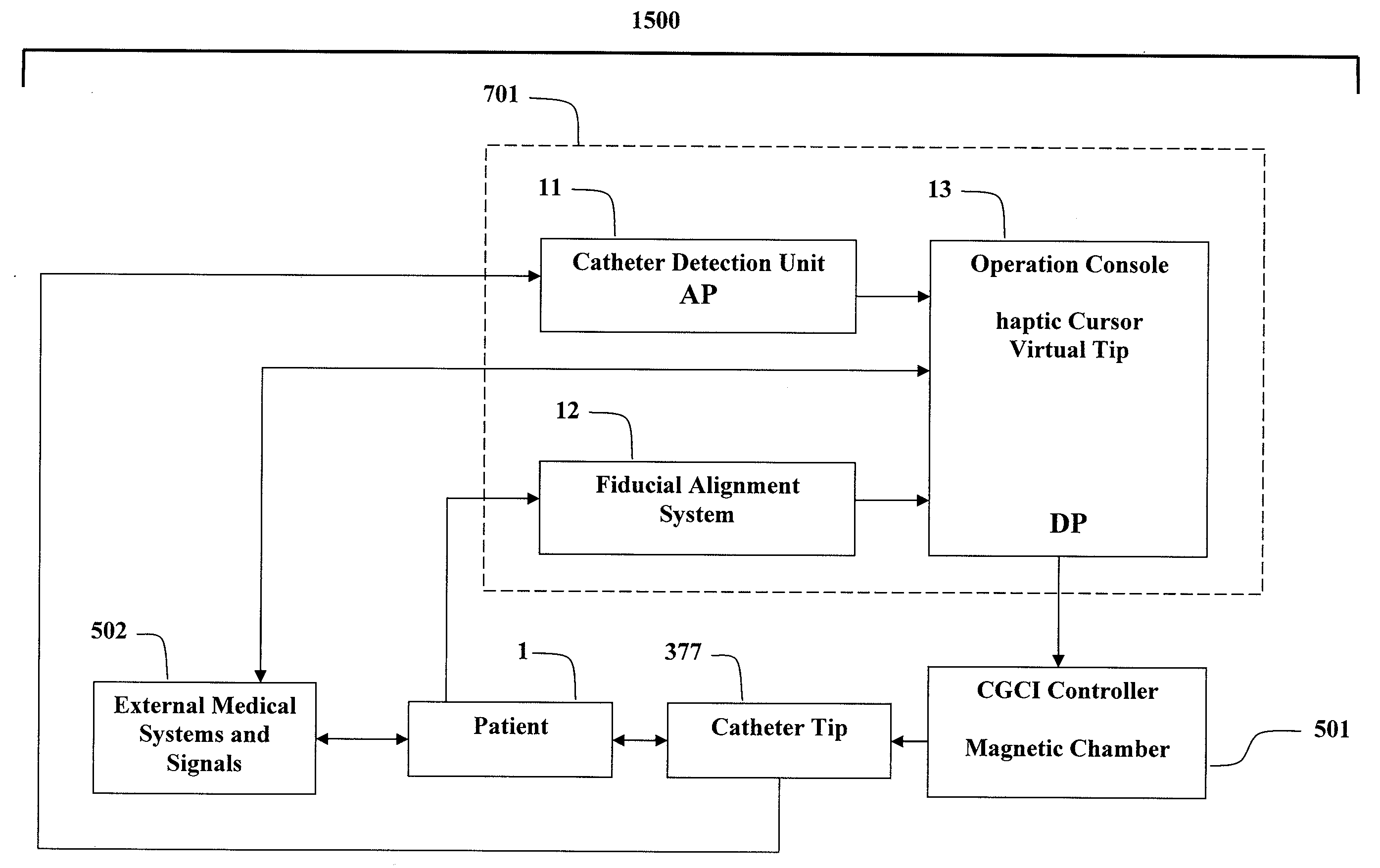
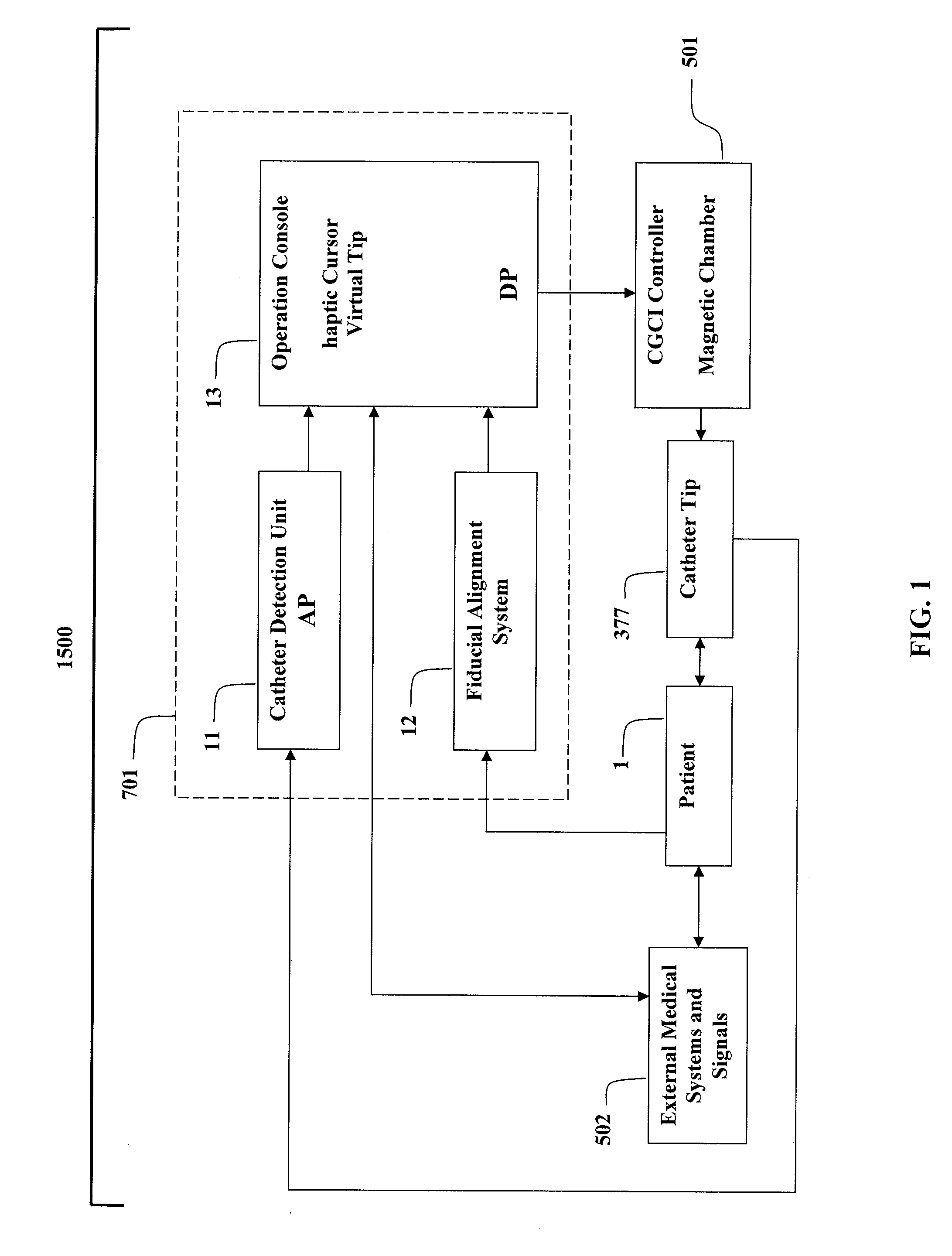
[0069]FIG. 1 is a block diagram of a CGCI unit 1500 what includes an imaging and synchronization unit 701, a catheter detection unit 11, a fiducial alignment system 12, and an operation console 13. In the CGCI Unit 1500, the operator navigates a magnetically tipped catheter 377 within a patient 1 using a six-degree of freedom haptic joystick 18 (shown in FIG. 9) while visualization of the progress of a virtual catheter tip 905 within the operation console's three dimensional virtual environment 13 as shown in FIG. 6. The catheter tip position detection system 11 provides the current position of the catheter tip or actual position (AP) 902, and the operator's position movement commands to move the catheter to a desired position (DP) 903 are sent to the catheter tip position control system or the CGCI controller 501 in FIG. 1.

[0070]Use of a magnetic chamber with an adaptive regulator, while using a joystick haptic device for operator control and method for detecting a magnetically tip...


PUM


Abstract

A method and apparatus for detecting position and orientation of catheter distal magnetic element end while moving in a patient's heart is described. The apparatus includes magnetic sensors for to detect the magnetic field of a generated by the catheter tip. Each sensor transmits the field magnitude and direction to a detection unit, which filters the signals and removes other field sources, such as generated by CGCI coils and external medical hardware. The method allows the measurements of magnitude corresponding to the catheter tip distance from the sensor and the orientation of the field showing the magnetic tip orientation. Since the tip's magnetic field is not necessarily symmetric, the position and orientation computation technique are not independent of each other. Hence, an iterative calculation is used to converge to a solution. The method of determining tip position is calculated by triangulation from each sensor. In one embodiment, the tip orientation is calculated by an intersecting-planes algorithm. The orientation is used to adjust the distances from each sensor, and the process is repeated until convergence for both position and orientation is achieved. The resultant value provides the actual catheter tip position and orientation (AP). The actual position is further filtered by synchronizing the AP measurements with the QRS signal of the heart, allowing the operator and CGCI controller to view the organ as a static object.

Description

BACKGROUND[0001]1. Field of the Invention[0002]The invention relates to systems and methods for guiding, steering, and advancing an invasive medical device in a patient while using a sensor and fiducial markers to determine the location and orientation of the catheter.[0003]2. Description of the Prior Art[0004]Catheterization is typically performed by inserting an invasive device into an incision or body orifice. This procedure relies on manually advancing the tip of the invasive device by pushing, rotating, or otherwise manipulating the proximal end which remains outside of the body.[0005]The prior art approach to solving the fiducial relationship between the moving catheter tip and the heart relies on manually advancing the catheter tip by pushing the proximal end of the catheter, while grossly neglecting the respiratory outputs (ribcage displacement), heart contraction, QRS synchronization, patient operating bed location, image capture (x-ray or other imaging modalities) to appro...

Claims


Application Information

Patent Timeline
IPC IPC(8): A61B5/05
CPCA61B5/06A61B5/062A61B5/7285A61B19/52A61B19/5244A61B19/56A61B2017/00703A61B2019/2292A61B2019/502A61B2019/505A61B2019/507A61B2019/5251A61B34/20A61B34/25A61B34/76A61B90/36A61B2034/102A61B2034/105A61B2034/107A61B2034/2051
Inventor SHACHAR, YEHOSHUAMARX, BRUCEFARKAS, LESLIE
Owner NEURO KINESIS CORP
Why Eureka
Try Eureka