
Vascular Catheter Device and Related Methods of Using the Same

a catheter device and vascular technology, applied in balloon catheters, medical science, surgery, etc., can solve problems such as vascular trauma, and achieve the effects of reducing risk, reducing complications, and reducing complications

Inactive Publication Date: 2008-10-09
CROSSMAN ARTHUR W
View PDF61 Cites 27 Cited by
  • Summary
  • Abstract
  • Description
  • Claims
  • Application Information

AI Technical Summary

Benefits of technology

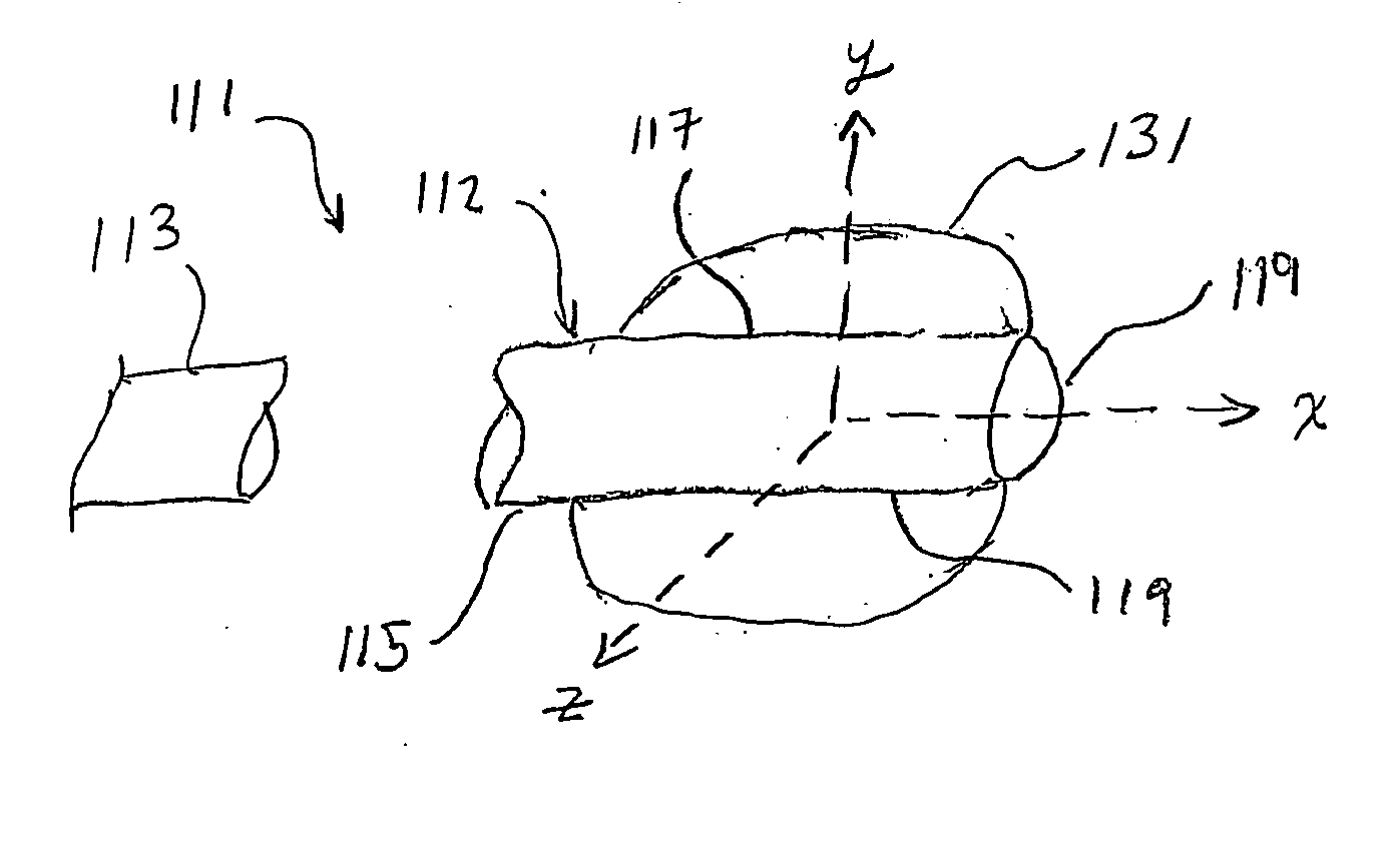
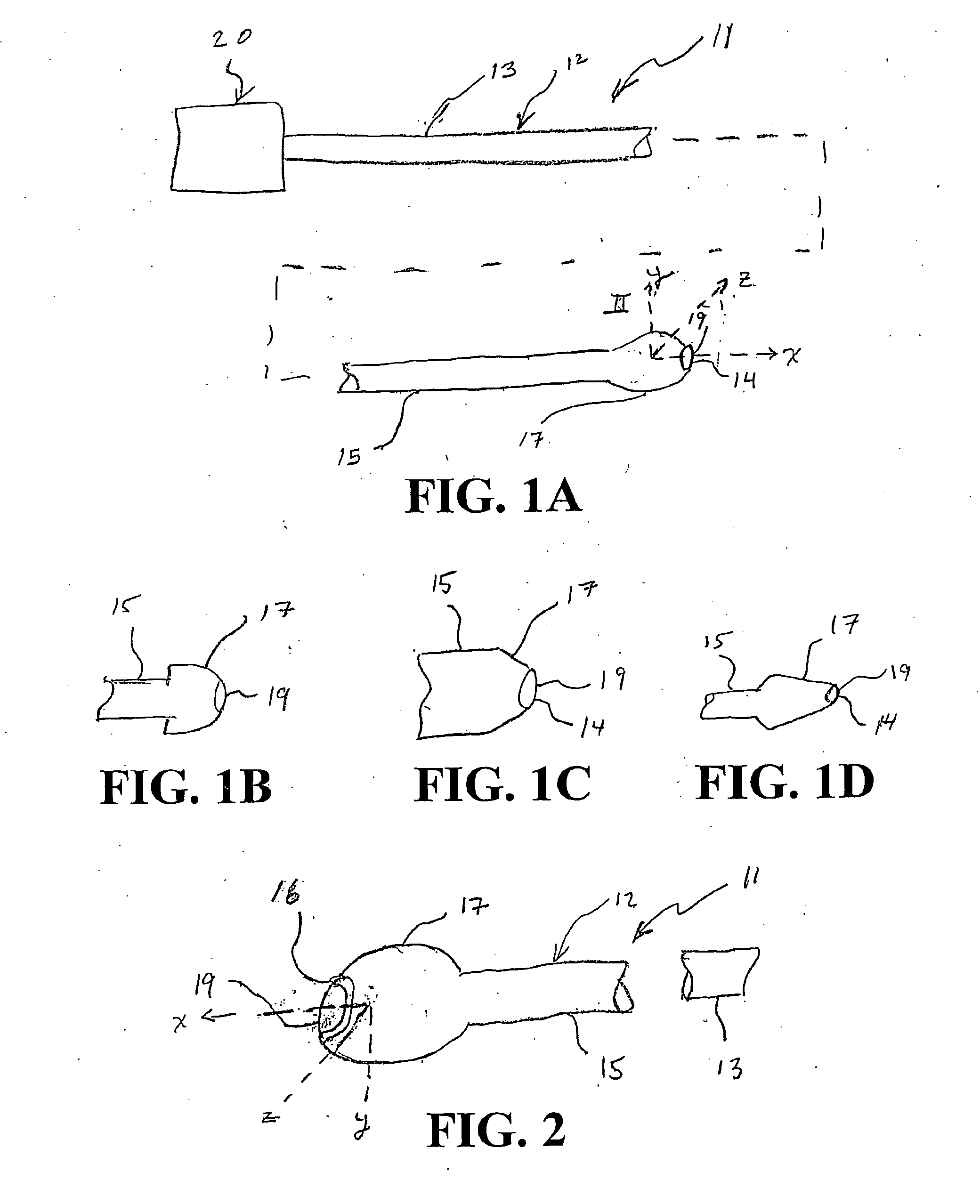
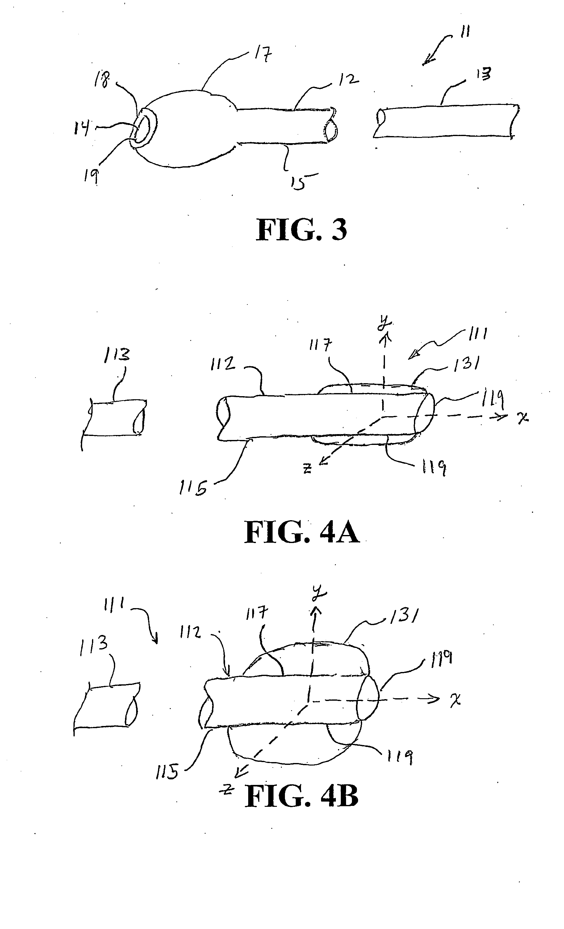
[0007]The various embodiments of the present invention are to provide a blunt, atraumatic (non-traumatic) distal tip and orifice edge to the catheter. This will eliminate or mitigate catastrophic complications caused by contemporary catheters such as vascular dissection, thrombosis, distal embolization and vessel occlusion. The various embodiments of the present invention catheter tip can be shaped in various ways with solid material (compressible or non-compressible) or balloon inflation devices to create a blunt, atraumatic (non-traumatic) tip and orifice. The shape can take on numerous forms including, but not limited to olive, bulbous, rounded, spherical, hemispherical, conical, oval, tapered, beveled, chamfered, graduated, ring, tubular, cylinder and / or multi-faceted like a cut diamond (as well as dodecaliedron, semi-dodecahedron, icosahedron, or semi- icosahedron, etc.). The present invention device and method would enable atraumatic intubation of all vascular structures. Some advantages associated with some of the embodiments include, but not limited thereto, elimination or mitigation of risks of the aforementioned complications as compared to conventional catheters and provide more aggressive intubation of vascular structures for improved leverage for delivery of therapeutic interventional hardware (i.e. balloons, stents, atherectomy devices, lasers, thrombectomy devices, etc.) in situations where conventional catheters may traumatize the vessel or fail to deliver the therapeutic hardware; secondary to concern for risk of vascular trauma and the aforementioned complications.

Problems solved by technology

This may lead to vascular trauma due the relatively sharp edge of the catheter disrupting the layers of the vessel Or plaque shoulder secondary to pressure exerted and or inherent angulation of the edge interface with the vessel wall.

Method used


Image

  • Vascular Catheter Device and Related Methods of Using the Same
  • Vascular Catheter Device and Related Methods of Using the Same
  • Vascular Catheter Device and Related Methods of Using the Same

Examples


Embodiment Construction

[0024]Some of the embodiments of the present invention provide a diagnostic vascular catheter for imaging or a therapeutic vascular catheter for vascular lumen enlargement that is atraumatic by providing, among other things, the tip of the catheter blunt in shape. It should be appreciated that the embodiments of the present invention distal tip can be utilized with the existing arterial vascular imaging and therapeutic catheters in terms of their proximal portion of the catheter and shaft shape of the catheter with regards to design, and materials. It should be appreciated that some of the embodiments of the present invention distal tip and balloons can utilize materials available in the field.

[0025]In an embodiment of the present invention catheter, the distal tip and tip orifice includes, but not limited thereto, the following: 1) solid non-compressible blunt tip and orifice / orifice edge (perimeter, partial perimeter or the like). The material of the non-compressible tip can be co...


PUM


Abstract

A catheter device fur diagnostic vascular treatment and / or therapeutic vascular treatment of a subject's vasculature having a blunt, atraumatic (non-traumatic) distal tip and orifice edge to the catheter. This will eliminate or mitigate catastrophic complications caused by contemporary catheters such as vascular dissection, thrombosis, distal embolization and vessel occlusion. The catheter tip can be shaped in various ways with solid material (compressible or non-compressible) or balloon inflation devices to create a blunt, atraumatic (non-traumatic) tip and orifice, and may include a set-back region as well.

Description

CROSS-REFERENCE TO RELATED APPLICATIONS[0001]The present invention claims priority under 35 U.S.C. Section 119(e) of the earlier filing date of U.S. Provisional Application Ser. No. 60 / 618,695, filed Oct. 14, 2004, entitled “Vascular Catheter Device and Related Method of Making and Using the Same,” which is hereby incorporated by reference herein in its entirety.BACKGROUND OF THE INVENTION[0002]Diagnostic vascular catheterization is a classification of invasive procedures in which a catheter and related are passed into a peripheral vein or artery, through the blood vessels, and into the heart or other vasculature. These procedures permit the study of the heart chambers and the arteries supplying the heart or other vasculatures of the body to diagnose illness or disease. Some examples of diagnostic vascular catheterization are, but not limited thereto, are coronary and peripheral vascular (e.g., renal artery, iliofemoral, aortic, cerebrovascular) angiography (or coronary arteriogaphy...

Claims


Application Information

Patent Timeline
IPC IPC(8): A61M25/10A61B5/02A61M25/01A61F2/958
CPCA61M25/0068A61M25/1002A61M2025/0081A61M2025/1072
Inventor CROSSMAN, ARTHUR W.
Owner CROSSMAN ARTHUR W
Learn More