Patient-specific cortical surface tessellation into dipole patches

Pending Publication Date: 2022-04-07
KONINKLJIJKE PHILIPS NV
View PDF0 Cites 1 Cited by
  • Summary
  • Abstract
  • Description
  • Claims
  • Application Information

AI Technical Summary

Benefits of technology

[0005]One object of the present invention is to improve upon current methods of cortical surface tessellation. To better address such concerns, in a first aspect of the invention, a method that tessellates a cortical surface with a plurality of dipole patches, wherein a quantity of the plurality o

Problems solved by technology

Electroencephalograph source localization is generally considered an underdetermined problem because of

Method used


Image

  • Patient-specific cortical surface tessellation into dipole patches
  • Patient-specific cortical surface tessellation into dipole patches
  • Patient-specific cortical surface tessellation into dipole patches

Examples


Embodiment Construction

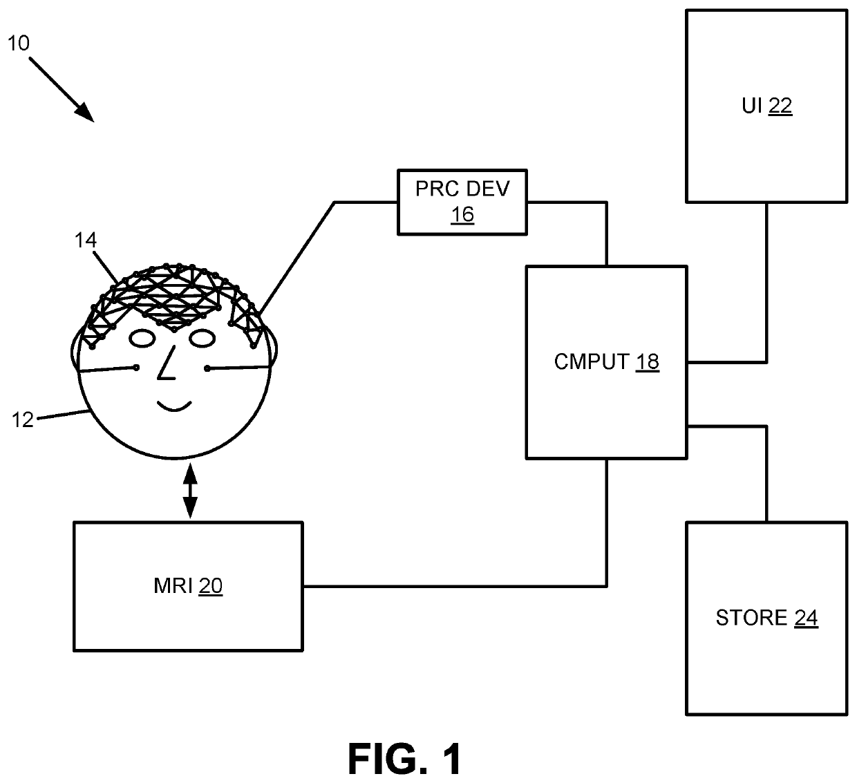
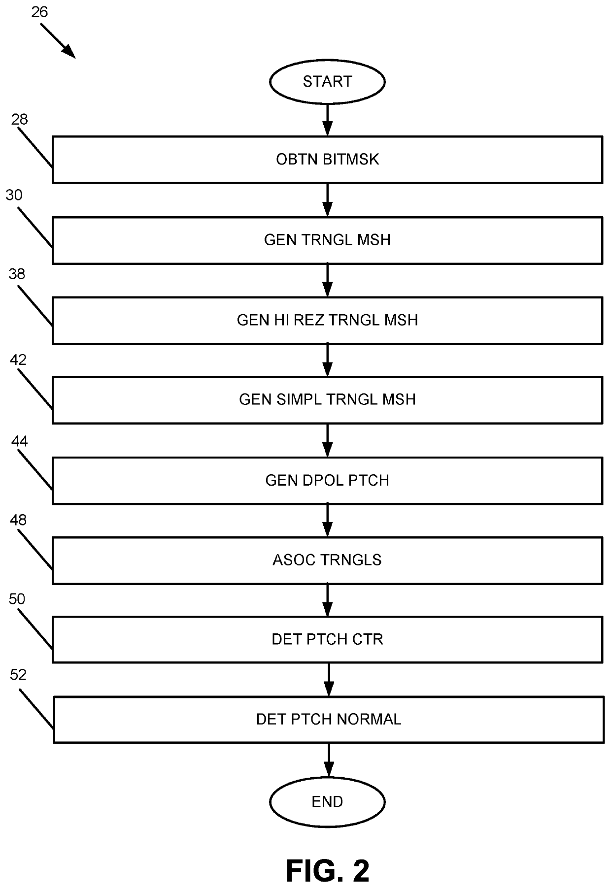
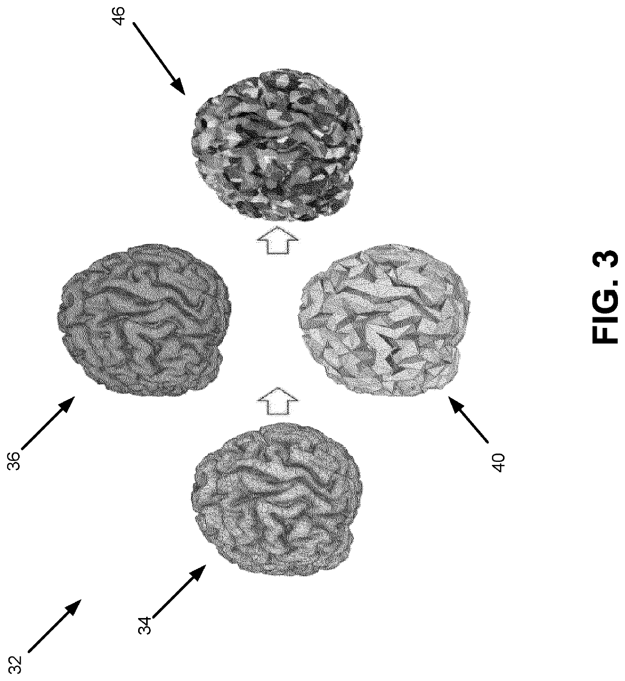
[0019]Disclosed herein are certain embodiments of a cortical surface tessellation method (and associated apparatus and system) that provides for (an automatic) tessellation of a cortical surface into dipole patches necessary for accurate electrical source imaging (ESI) localization. Certain embodiments of a cortical surface tessellation method provide for an accurate representation of the propagation of electrical activity from the cortex to the scalp by virtue of having dipole patches with normals perpendicular to all triangles in the patch, and the number of patches depending on the head size.

[0020]Digressing briefly, current dipole tessellation methods limit the number of dipole patches to a predefined constant, which results in dipole patches that cover gyri and sulci simultaneously. In other words, one or more of the dipole patches may each span several gyri and sulci, resulting in incorrect dipole normals. In contrast, certain embodiments of a cortical surface tessellation met...


PUM


Abstract

A method (26) that tessellates a cortical surface of a brain with a plurality of dipole patches, wherein a quantity of the plurality of dipole patches is variable and dependent upon a head size.

Description

FIELD OF THE INVENTION[0001]The present invention is generally related to electrical source imaging, and in particular, formulating a forward model used in electrical source imaging.BACKGROUND OF THE INVENTION[0002]Epilepsy is a public health problem that affects almost 3 million individuals in the US alone. Surgery is the most effective treatment for medically intractable epilepsy and can be curative if the seizure focus can be localized. Minimally invasive interventions to remove a seizure focus have significant advantages over open head surgery, including resulting in greater preservation of tissue and having better overall functional outcomes. Both minimally invasive ablations and open head surgeries require the use of high-resolution, structural magnetic resonance imaging (MRI) to identify and visualize the seizure focus. Electrical source imaging (ESI) is a neuroimaging technique. ESI from electroencephalography (EEG) electrodes positioned on the scalp can localize the seizure...

Claims


Application Information

Patent Timeline
IPC IPC(8): G06T17/20G06T7/10A61B5/291A61B5/00
CPCG06T17/20G06T7/10A61B5/291G06T2207/30016G06T2210/41G06T2207/10088A61B5/6814G06T17/00
Inventor ZAGORCHEV, LYUBOMIR GEORGIEV
Owner KONINKLJIJKE PHILIPS NV
Why Eureka
Try Eureka