Screening system

a screening system and vibrating screen technology, applied in screening, screening, grading, etc., can solve the problems of extremely expensive and restricted platform real estate, and achieve the effect of reducing the size of the apparatus required to process a given volume of feed, increasing the effective screen surface area, and reducing the size of the apparatus

Active Publication Date: 2008-10-16
NAT OILWELL VARCO UK
View PDF49 Cites 24 Cited by
  • Summary
  • Abstract
  • Description
  • Claims
  • Application Information

AI Technical Summary

Benefits of technology

[0005]With an apparatus of the present invention, the size of apparatus required to process a given volume of feed is substantially reduced compared with conventional apparatus, since a substantially increased effective screen surface area can be accommodated with relatively little or no increase in the size of the apparatus by means of stacking a plurality of screen assemblies within a single basket and using a flow distributor to route multiple flows in parallel through different screens in the stack.
[0006]Advantageously the distributor is formed and arranged so as to be switchable between a plurality of different flow directing configurations. Conveniently said plurality of flow directing configurations includes an intensive screening configuration in which the whole of the feed is directed onto said first screen assembly and the whole of the filtrate from said first screen assembly is directed onto said second screen assembly. Alternatively or additionally there is provided a restricted feed capacity configuration in which the whole of the feed is directed onto only one of said first and second screen assemblies, and the filtrate therefrom exhausted directly from the apparatus without passing through the other one said first and second screen assemblies. Such a configuration is useful for basic fluid processing where high efficiency or high volume processing are not required and a reduced number of screens in operation reduces operating cost for screens consumed.

Problems solved by technology

A particular problem in offshore platform oil drilling is, however, that platform real estate is very restricted and extremely expensive.

Method used


Image

  • Screening system
  • Screening system
  • Screening system

Examples


Embodiment Construction

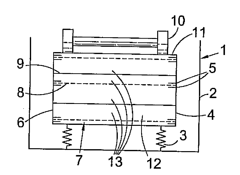
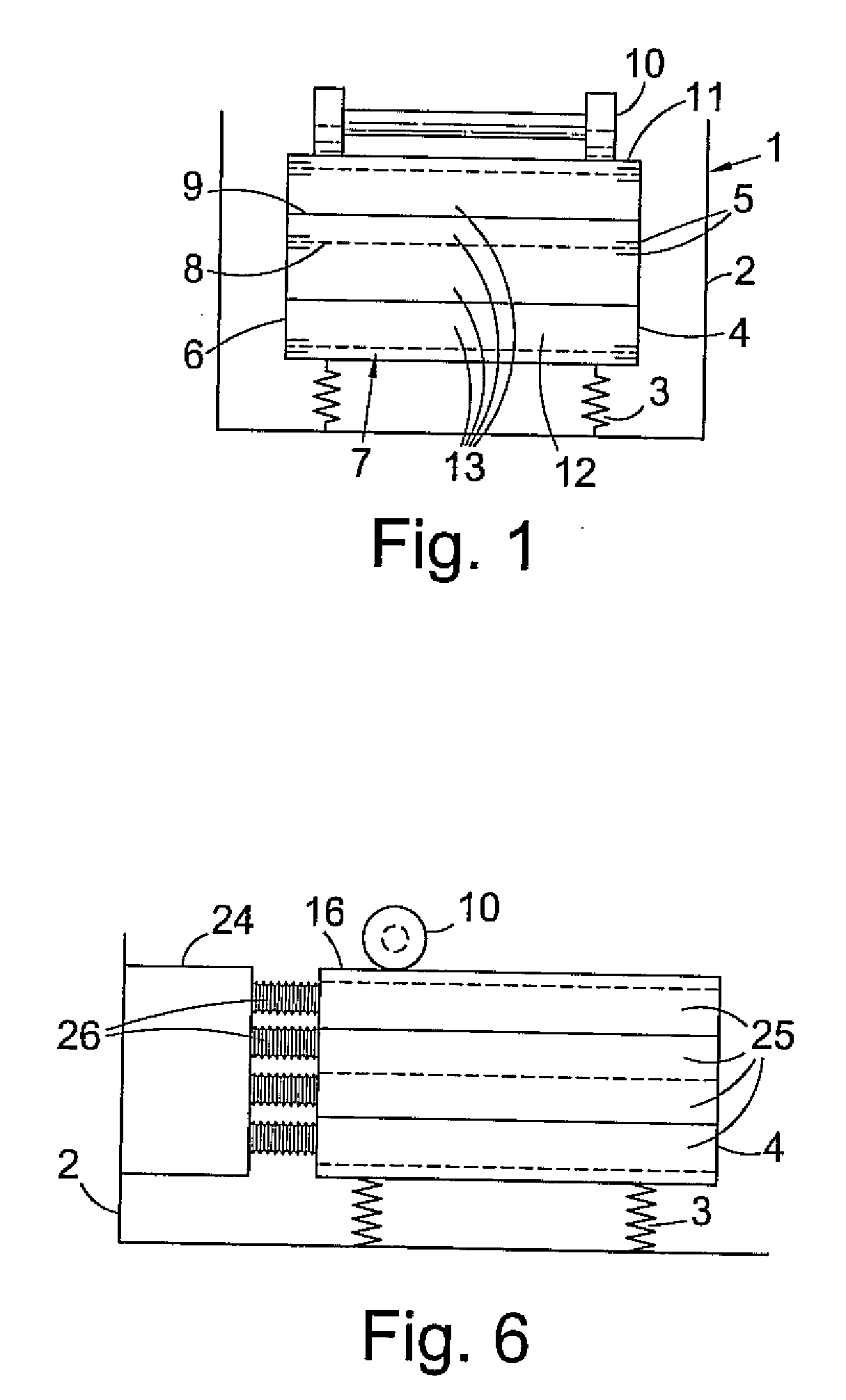
[0027]FIG. 1 shows schematically one embodiment of a vibratory screen apparatus 1 of the invention with an outer housing (indicated schematically) 2, in which is mounted on springs 3, a basket 4. (See below for more detailed description of housing.) The basket is generally box shaped with pairs of circumferentially extending inwardly projecting flanges 5 height on the basket side walls 6, for supporting respective ones of a stack 7 of screen assemblies 8 separated by flow directing trays 9. A vibrator unit 10 is secured to the top 11 of the basket. (Alternatively, the vibrator 10 could be mounted on a side of the basket 4, or incorporated into or within the structure of the basket 4. The interior 12 of the basket 4 is divided into a series of levels 13 between neighbouring screen assemblies 8 and flow directing trays 9.

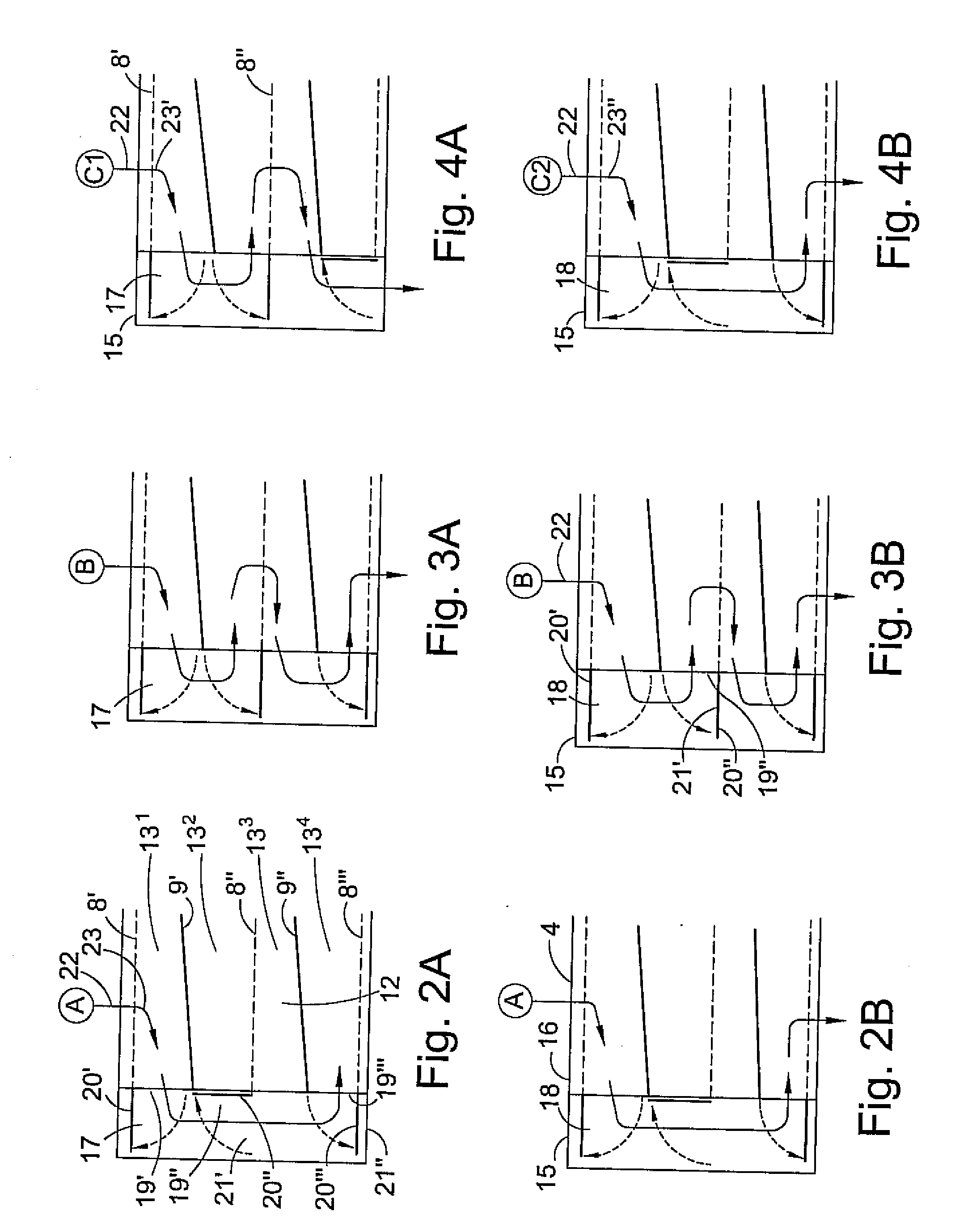
[0028]FIGS. 2A / B to 4A / B show schematically a distributor 15 provided at one end 16 of the floating basket 4. The distributor 15 is formed and arranged into inside an...


PUM

PropertyMeasurementUnit
sizeaaaaaaaaaa
particle size fractionaaaaaaaaaa
physical sizeaaaaaaaaaa

Abstract

The present invention provides a vibratory screening apparatus (1) for use in removing solids from a liquid feed, and a basket (4) therefore. The apparatus comprises a static outer housing (2), and a floating basket vibratable by a vibrator device (10). The basket mounts a stack (7) of screen assemblies (8) provided with respective flow directing trays (9) for receiving filtrates from the screen assemblies. A flow distributor (15) divides the feed into at least first and a second feed streams and directs them onto respective screen assemblies, and receives from the flow directing trays, filtrates from respective screen assemblies.

Description

CROSS-REFERENCE TO RELATED APPLICATIONS[0001]This application is a continuation of U.S. patent application Ser. No. 10 / 561,331 filed Dec. 16, 2003, which is a 371 of PCT / GB04 / 02544 filed Jun. 14, 2004, which claims priority of United Kingdom Patent Applications 031321.7 filed Jun. 12, 2004 and 329920.3 filed Dec. 24, 2003.FIELD OF THE INVENTION[0002]The present invention relates to vibratory screening apparatus suitable for use with drilling fluids, mineral processing, classification, and dewatering, and the like.BACKGROUND OF THE INVENTION[0003]Vibratory screening apparatus is widely used in the oil drilling industry for removing drill cuttings from drilling fluids, and over the years various improvements have been made to the screens used therein, methods for mounting the screens etc to improve ease of use, reduce maintenance etc. A particular problem in offshore platform oil drilling is, however, that platform real estate is very restricted and extremely expensive. There is accor...

Claims


Application Information

Patent Timeline
Patent Type & Authority Applications(United States)
IPC IPC(8): B07B1/28
CPCB01D33/0338B07B1/46B07B13/16B07B2201/04E21B21/01E21B21/065B01D33/0376B01D33/39
Inventor BAILEY, MARSHALL GRAHAM
Owner NAT OILWELL VARCO UK
Why Eureka
Try Eureka