Pressure Control Valve

a technology of pressure control valve and control valve, which is applied in the direction of process and machine control, lighting and heating apparatus, instruments, etc., can solve the problems of difficult to reduce the cost of assembling the system as a whole, and achieve the effect of reducing the number of parts, reducing the cost of assembling the system, and ensuring the quality of the assembling process

Inactive Publication Date: 2008-10-16
FUJIKOKI CORP +1
View PDF10 Cites 13 Cited by
  • Summary
  • Abstract
  • Description
  • Claims
  • Application Information

AI Technical Summary

Benefits of technology

[0004]Even in the pressure control valve constructed as described above as well as in the refrigeration cycle provided with such a pressure control valve, there are increasing and persistent demands in recent years for the reduction of manufacturing cost, so that it is now strongly desired to simplify the structure thereof, to reduce the number of parts, and to reduce the processing and assembling costs.
[0005]In the case of the refrigeration cycle provided with the conventional pressure control valve in particular, the pressure control valve is interposed between the gas cooler and the inner heat exchanger, so that the refrigerant on the exit side of the gas cooler is enabled to be directly introduced into the pressure control valve, enabling the temperature of the refrigerant to be sensed by the temperature-sensitive / pressure-responsive element, and then the refrigerant is delivered to the inner heat exchanger to execute the heat exchange thereof and, after this heat exchange, returned again to the pressure control valve so as to be regulated in pressure, this pressure-regulated refrigerant being subsequently delivered to an evaporator. Therefore, the pressure control valve is required to be equipped with a total of four refrigerant inlet and outlet ports, i.e. a temperature-sensing inlet port, a temperature-sensing outlet port, a pressure-regulating inlet port and a pressure-regulating outlet port. As a result, the piping system for the pressure control valve as well as for the refrigeration cycle is complicated in construction, thus making it difficult to reduce the cost for assembling the system as a whole.
[0006]The present invention has been made to meet the aforementioned demands, and therefore an object of the present invention is to provide a pressure control valve which is capable of appropriately regulating the pressure of the refrigerant on the exit side of the gas cooler and also capable of effectively simplifying the structure thereof, reducing the number of parts and reducing the processing and assembling costs. A further object of the present invention is to provide a refrigeration cycle comprising such a pressure control valve.

Problems solved by technology

As a result, the piping system for the pressure control valve as well as for the refrigeration cycle is complicated in construction, thus making it difficult to reduce the cost for assembling the system as a whole.

Method used


Image

  • Pressure Control Valve
  • Pressure Control Valve
  • Pressure Control Valve

Examples


first embodiment

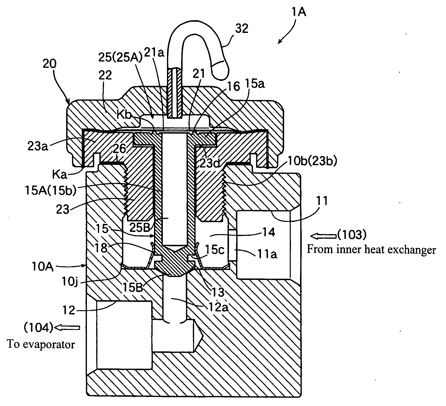
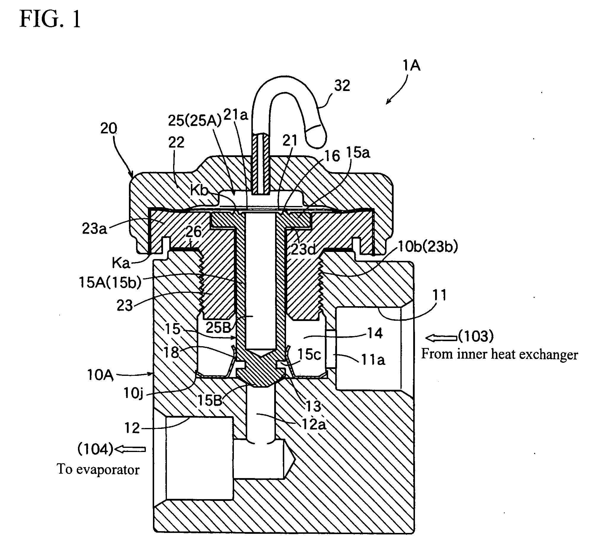
[0054]FIGS. 1 and 2 are a longitudinal cross-sectional view and a right side view, respectively, both illustrating the pressure control valve according to the present invention.

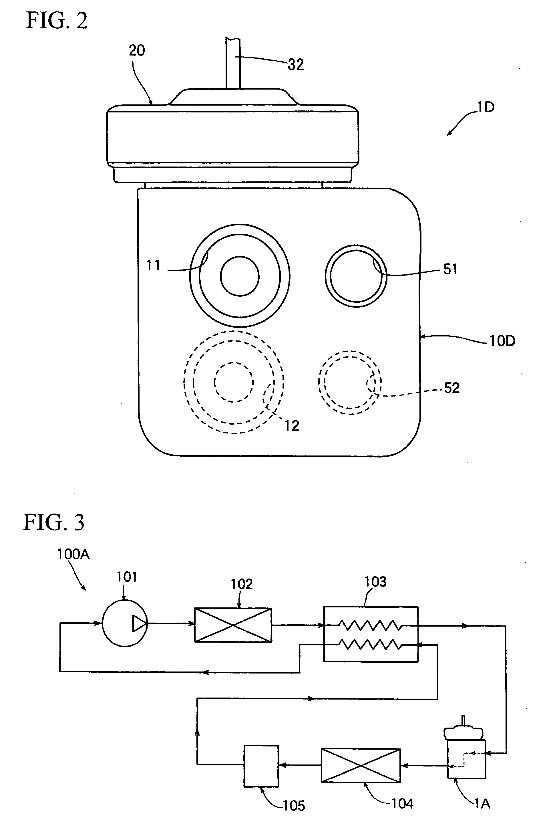
[0055]As shown in FIG. 3, the pressure control valve 1A according to a first embodiment is built in a vapor compression refrigeration cycle 100A which is fundamentally constituted by the same constituent elements as those shown in FIG. 19 mentioned above, but in such a different manner from the vapor compression refrigeration cycle shown in FIG. 19 that the pressure control valve 1A is interposed between the inner heat exchanger 103 and the evaporator 104 (in the prior art, the pressure control valve is interposed between the gas cooler 102 and the inner heat exchanger 103).

[0056]Therefore, the refrigerant to be introduced into the pressure control valve 1A from the gas cooler 102 through the inner heat exchanger 103 is enabled to be regulated in pressure in conformity with the temperature of refrigerant on t...

seventh embodiment

[0060]Herein, the refrigerant inflow port 11 and the refrigerant outflow port 12 are disposed parallel with each other and designed to serve also as temperature-sensing inlet / outlet ports and as pressure-regulating inlet / outlet ports in the conventional pressure control valve. By the way, small notches (see FIGS. 12 and 13 illustrating the seventh embodiment to be discussed hereinafter) are formed in the valve seat 13 and the opening degree of the pressure control valve 1A corresponds to the magnitude of lifting of the valve 15 (or the valve portion 15B thereof) from the valve seat 13.

[0061]The temperature-sensitive / pressure-responsive element 20 is constituted by a diaphragm 21 having a short cylindrical configuration with a closed end, by a cap member 22 having a convex cross-section and defining, in cooperation with the diaphragm 21, a temperature-sensitive chamber (diaphragm temperature-sensitive chamber) 25A, and by a cylindrical cap-receiving member 23 with a flange portion 23...

fourth embodiment

[0078]The pressure control valve 1D of a fourth embodiment shown in FIG. 8 is featured in that it is provided with a valve chamber 44 having the valve seat 13 and disposed at a location inside the valve body 10D which is more or less spaced away from the refrigerant introduction chamber 14, wherein the refrigerant introduction chamber 14 is communicated, through a plurality (four for instance) of small communicating holes 46, with the valve chamber 44 (see also FIG. 9).

[0079]More specifically, the valve 15 is constituted by a valve stem 15A having in-valve temperature sensitive chamber 25B formed therein, and an extension shaft 15E having a valve portion 15B press-inserted on and coupled with a lower end portion of the valve stem 15A. A valve chamber 44 is formed around a lower portion of this extension shaft 15E and a plurality of communicating holes 46 are provided around the valve chamber 44 at equiangular intervals.

[0080]Since the pressure control valve 1D is constructed in this...


PUM


Abstract

There is disclosed a pressure control valve comprising: a valve body (10A) provided successively with, mentioning from the upstream side in the flowing direction of refrigerant, a refrigerant inflow port (11), a refrigerant introduction chamber (14), a valve seat (13) with which a rod-like valve (15) is retractably contacted, and a refrigerant outflow port (12); and a temperature-sensitive / pressure-responsive element (20) which is provided with a temperature sensitive chamber (25) for sensing the temperature of the refrigerant that has been introduced into the refrigerant introduction chamber (14) and is designed to drive the valve (15) in opening or closing direction in response to fluctuations of the inner pressure of the temperature sensitive chamber (25). The temperature-sensitive / pressure-responsive element (20) is integrally attached to the valve body (10A).

Description

TECHNICAL FIELD[0001]This invention relates to a pressure control valve which is suited for use in a vapor compression refrigeration cycle using CO2 as a refrigerant (CO2 cycle) or especially suited for use in a vapor compression refrigeration cycle provided with an inner heat exchanger which is designed to be employed in an automobile air conditioner for performing heat exchange between the refrigerant on the exit side of an evaporator and the refrigerant on the exit side of a gas cooler.BACKGROUND ART[0002]FIG. 19 shows one example of the vapor compression refrigeration cycle wherein a pressure control valve of this kind is built therein. The refrigeration cycle 100 shown herein is constituted: by a compressor 101 for circulating CO2 as a refrigerant; a gas cooler (radiator) 102 for cooling the refrigerant that has been compressed by the compressor 101; an evaporator 104 into which the refrigerant is enabled to enter from the gas cooler 102; an inner heat exchanger 103 for perform...

Claims


Application Information

Patent Timeline
Patent Type & Authority Applications(United States)
IPC IPC(8): F16K31/00F16K31/126F25B41/00F25B41/04
CPCF25B40/00F25B41/062F25B2309/061F25B2341/063F25B2341/0683F25B2500/01G05D23/022F25B41/335
Inventor ISE, SADATAKEYANAGISAWA, SHUTOMARU, MASAKIKATAYAMA, TOSHIHARU
Owner FUJIKOKI CORP
Why Eureka
Try Eureka