
Sensorless driving method for brushless DC motor

a brushless dc motor and sensorless technology, applied in the direction of motor/generator/converter stopper, electronic commutator, dynamo-electric converter control, etc., can solve the problems of reducing the reliability of the sensor and the commutating control, increasing the volume and cost of the system with the sensor installed, and reducing the space taken by the position sensor. , to achieve the effect of low nois

Inactive Publication Date: 2008-10-16
IND TECH RES INST
View PDF10 Cites 14 Cited by
  • Summary
  • Abstract
  • Description
  • Claims
  • Application Information

AI Technical Summary

Benefits of technology

The present invention provides a sensorless driving method for a brushless DC motor that reduces electronic noise caused by phase shifts and uses a mask-based phase shift digital detection mechanism for detecting zero-crossing and an inhibition mechanism for inhibiting electronic noise caused by transistor switching. The method also includes a soft-switch method for reducing noise caused by transistor switching while the motor commutating. The soft-switch method detects the electrical angle before and after a commutating point and reduces the PWM duty cycle within an electrical angle to reduce voltages of the motor coils. The technical effects of the invention are no sensor and low noise, improved performance and efficiency of brushless DC motors.

Problems solved by technology

Therefore, to increase the resolution of the sensor and the accuracy of commutating control, both the volume and cost of the system with the sensor installed are increased.
The design of motor is going towards miniaturization, high precision, and low noise inevitably, and the space taken by the position sensor has become a major obstacle for reducing the volume of the motor.
In addition, a position sensor is sensitive to temperature and noise and has life problem, which reduces the reliability of the sensor and the commutating control, and accordingly restricts the application of the motor relatively.

Method used


Image

  • Sensorless driving method for brushless DC motor
  • Sensorless driving method for brushless DC motor
  • Sensorless driving method for brushless DC motor

Examples


Embodiment Construction

[0026]Reference will now be made in detail to the present preferred embodiments of the invention, examples of which are illustrated in the accompanying drawings. Wherever possible, the same reference numbers are used in the drawings and the description to refer to the same or like parts.

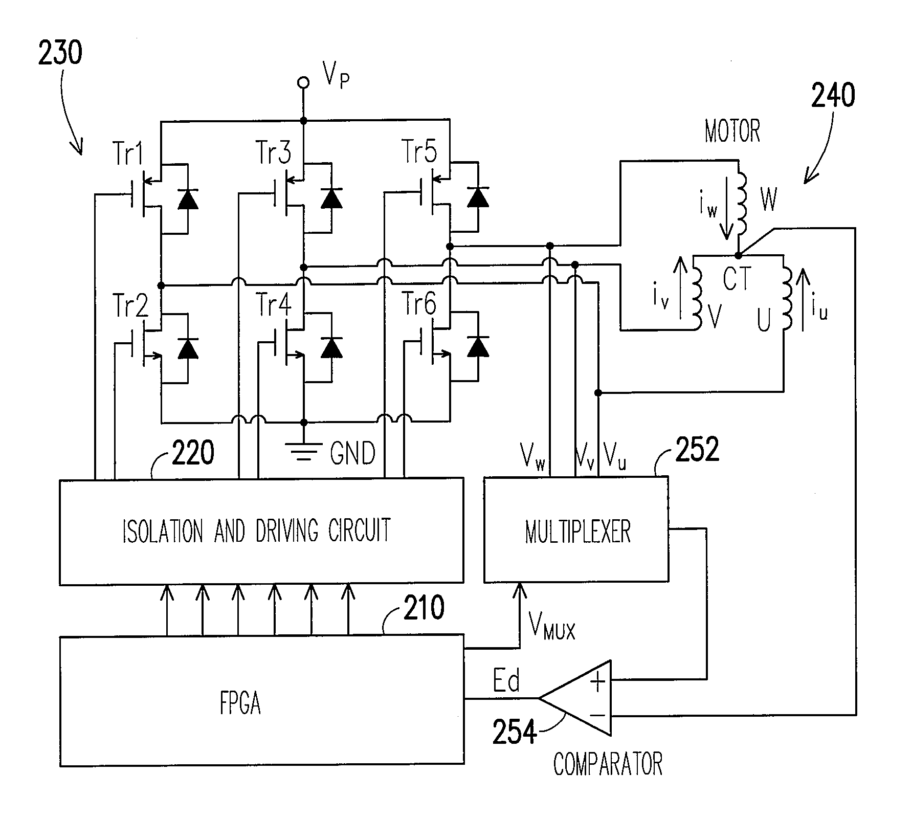
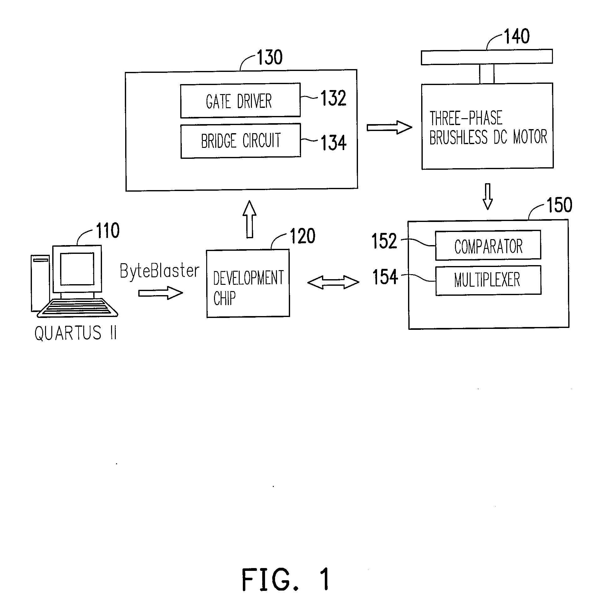
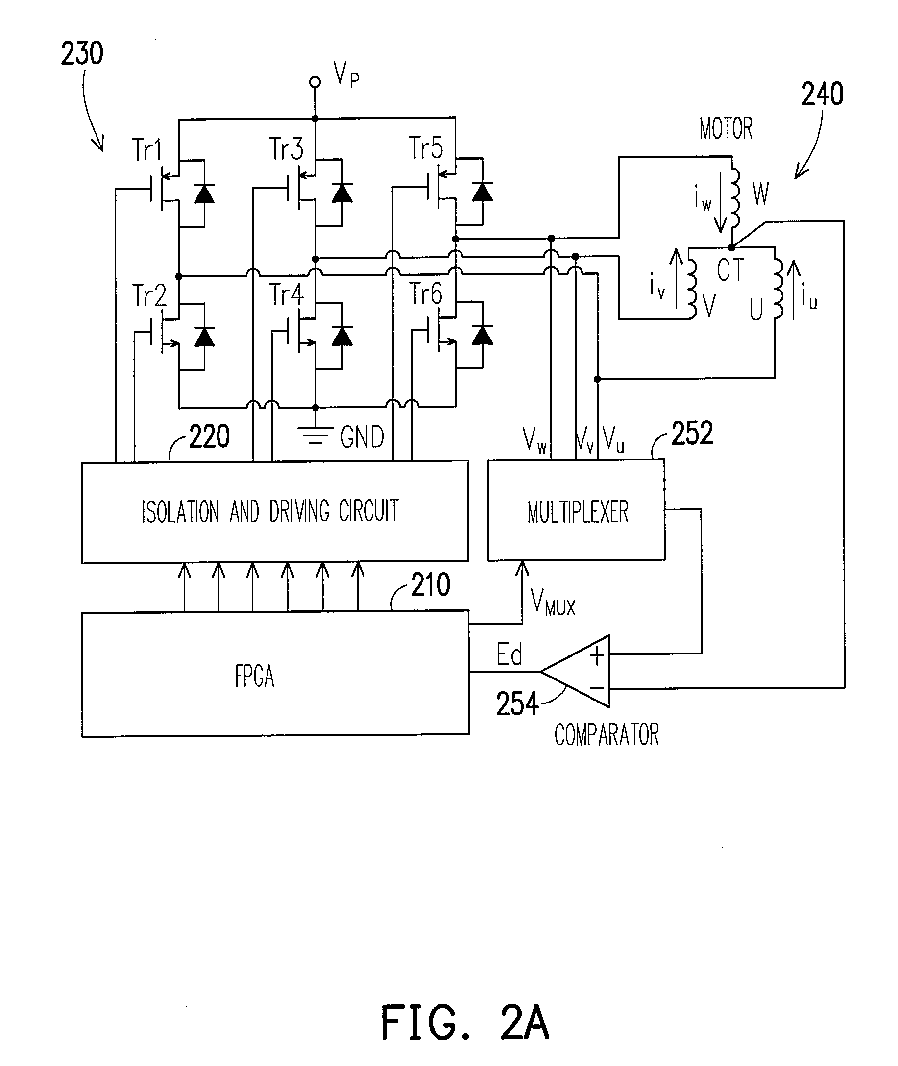
[0027]The present invention provides a sensorless driving method for a brushless DC motor, wherein the purpose of no sensor and low noise is achieved by using the terminal voltages and central phase voltage of the motor. The present invention also provides a method for driving a three-phase brushless DC motor without a sensor, and soft-switch is adopted in this method for reducing electronic noises caused by phase shifts.

[0028]According to the sensorless driving method for a brushless DC motor provided by the present invention, a mask-based phase shift digital detection mechanism and an inhabitation mechanism for inhibiting electronic noises caused by transistor switching are adopted.

[0029]According ...


PUM


Abstract

A sensorless driving method for a brushless DC motor is provided. The time for the motor to rotate an electrical angle 60° is obtained by alternatively counting the occurrences of zero crossings with two counters and comparing the counted values, and the motor is delayed an electrical angle of 30°, by which a precise commutating time is obtained. The driving method provides a mask-based phase shift digital detection mechanism for effectively detecting true zero-crossing points. The driving method further provides an inhabitation mechanism with the function of soft-switch for inhibiting noise caused by transistor switching. By using these two counters, the time for the motor to rotate two electrical angles 30°−Δθ and 30°+Δθ are obtained and stored in two registers. The time period before and after the commutating point is added into a pulse width modulation (PWM) signal to reduce the noise and vibration.

Description

CROSS-REFERENCE TO RELATED APPLICATION[0001]This application claims the priority benefit of Taiwan application serial no. 96105243, filed Feb. 13, 2007. All disclosure of the Taiwan application is incorporated herein by reference.BACKGROUND OF THE INVENTION[0002]1. Field of the Invention[0003]The present invention generally relates to a sensorless driving method for a brushless DC motor, in particular, to a sensorless driving method which achieves low noise by using the terminal voltage and central phase voltage of a motor.[0004]2. Description of Related Art[0005]A position sensor (for example, a Hall device) in a brushless DC motor is used for replacing the commutation structure (for example, a commutator and a carbon brush) in a conventional brush DC motor, therefore the brushless DC motor has such advantages as low noise, long life, and small volume etc. Besides, brushless DC motor has high rotating speed and requires no maintenance because no commutator or carbon brush is used; ...

Claims


Application Information

Patent Timeline
Patent Type & Authority Applications(United States)
IPC IPC(8): H02P6/14H02P7/06
CPCH02P6/142H02P6/18H02P6/15
Inventor YU, HSING-CHENGLIN, HSING-YULIN, SHIR-KUANWANG, SHYH-JIER
Owner IND TECH RES INST
Learn More