Projection display device

a technology of projection display and display device, which is applied in the direction of machines/engines, liquid fuel engines, instruments, etc., can solve the problems of reducing the versatility of vibration-proofing members, reducing the ease of handling, and increasing material costs and working costs, so as to reduce the ease of handling and increase material costs. the effect of working costs

Inactive Publication Date: 2008-10-16
SONY CORP
View PDF7 Cites 37 Cited by
  • Summary
  • Abstract
  • Description
  • Claims
  • Application Information

AI Technical Summary

Benefits of technology

[0007]The art disclosed in Japanese Patent Application Publication No. 2006-330300 is not without problems in various ways, due to the vibration-proofing member being formed in a ring-shape surrounding the perimeter of the fan case. For example, the vibration-proofing member needs to be large enough to surround the perimeter of the fan case. This leads to increase in material costs and working costs, while reducing ease of handling.

Problems solved by technology

The art disclosed in Japanese Patent Application Publication No. 2006-330300 is not without problems in various ways, due to the vibration-proofing member being formed in a ring-shape surrounding the perimeter of the fan case.
This leads to increase in material costs and working costs, while reducing ease of handling.
Also, fans of various sizes need to be used depending on the type of the projection display device, position where the fan is installed, and so forth, so multiple types of vibration-proofing members need to be provided in accordance with different sizes of fans, reducing versatility of the vibration-proofing members.
This also leads to increased costs.
Also, reducing the tolerance such that the vibration-proofing member is in close contact with the entire perimeter of the fan case increases working costs.
Conversely, increased tolerance means that the vibration-proofing member is not in close contact with the fan, and sufficient vibration-proofing effects may not be obtainable.

Method used


Image

  • Projection display device
  • Projection display device
  • Projection display device

Examples


Embodiment Construction

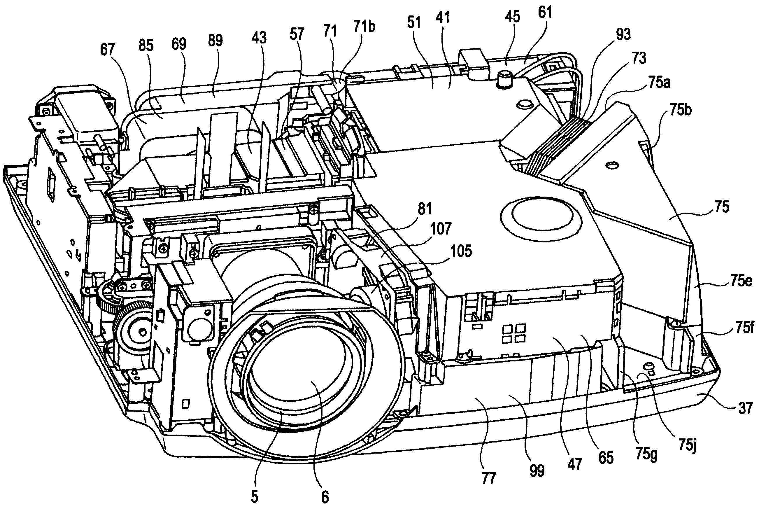
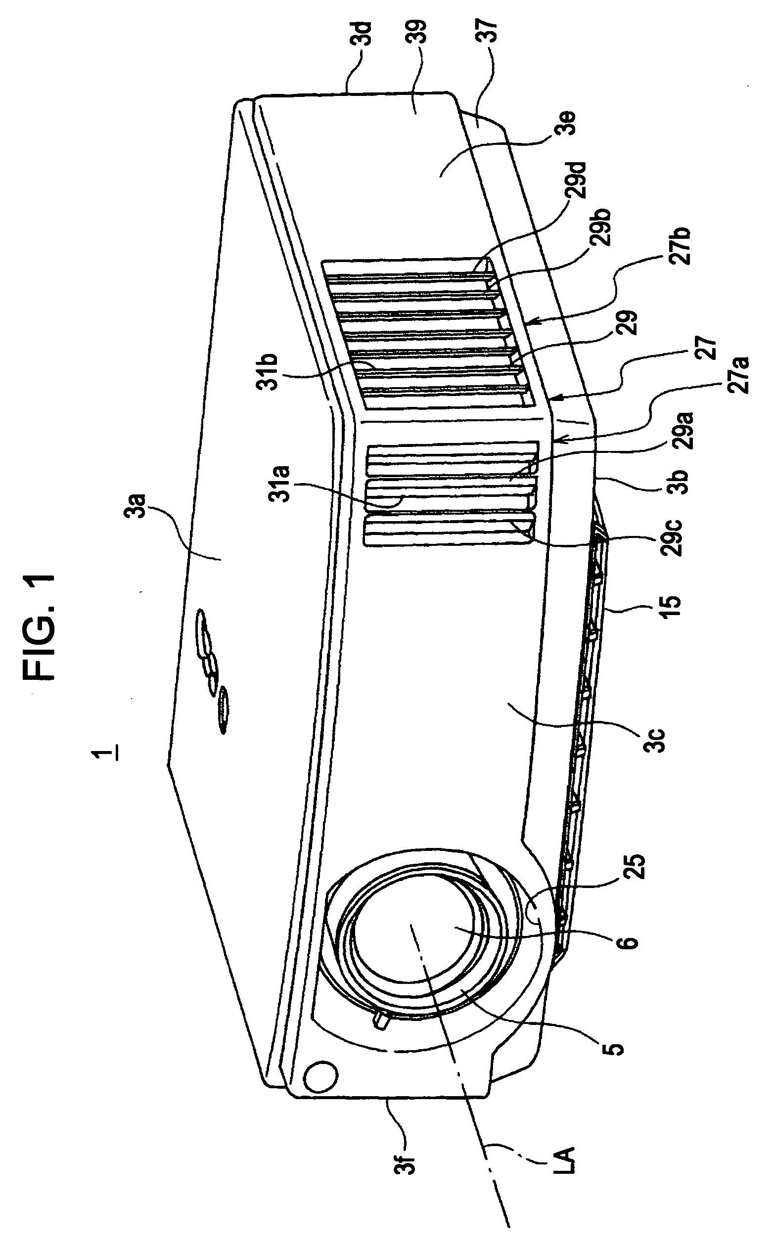
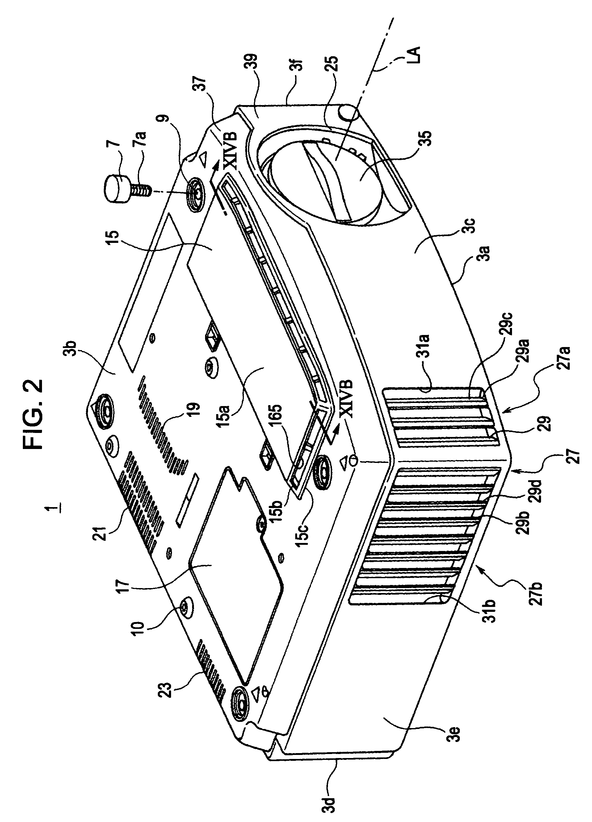
[0047]FIGS. 1 through 3 are perspective views illustrating the outside of a projector 11 serving as a projection display device according to an embodiment of the present invention. FIG. 1 is a perspective view of the projector 11 from the projection direction (screen side) and from above the projector 11, FIG. 2 is a perspective view of the projector 11 from the projection direction (screen side) and from below the projector 11, and FIG. 3 is a perspective view of the projector 11 from the rear (opposite to the screen side) and from below the projector 11.

[0048]Note that in the following description, configurations corresponding to light of each color, i.e., R light, G light, and B light may be denoted with symbols, R, G, and B, and these symbols may also be omitted as appropriate.

[0049]A projector 11 has a housing 3 and a lens barrel 5 attached to the housing 3 (FIG. 1). A projection lens 6 (FIG. 1) for projecting light onto a screen is disposed within the lens barrel 5. FIG. 2 exe...


PUM


Abstract

A projection display device includes: a housing; a fan disposed within the housing, the fan having a vane portion and a fan case accommodating the vane portion so as to be rotatable; and multiple vibration-proofing members having at least one of elasticity and viscosity, the vibration-proofing members being disposed at multiple positions in the circumferential direction of the perimeter face portion of the fan case surrounding the vane portion around the rotational axis of the vane portion, such that the vibration-proofing members are introduced between the housing and the fan case.

Description

CROSS REFERENCES TO RELATED APPLICATIONS[0001]The present invention contains subject matter related to Japanese Patent Application JP 2007-105287 filed in the Japanese Patent Office on Apr. 12, 2007, the entire contents of which are incorporated herein by reference.BACKGROUND OF THE INVENTION[0002]1. Field of the Invention[0003]The present invention relates to a projection display device such as a liquid crystal project, CRT projector, or the like, and more particularly relates to a projection display device of which the interior of the housing is air-cooled.[0004]2. Description of the Related Art[0005]With projection display devices, various parts are air-cooled, such as a light source, optical parts receiving light from the light source, and so forth. Vibrations from fans used for air-cooling cause various inconveniences, such as noise, adverse effects on electronic parts, and so forth. Accordingly, various configurations have been proposed as art for absorbing fan vibrations ther...

Claims


Application Information

Patent Timeline
Patent Type & Authority Applications(United States)
IPC IPC(8): G03B21/16
CPCG03B21/16
Inventor NAGAHATA, TAKASHIHIGUCHI, NOBUAKIITOU, YUUKIHARA, NOBUYUKI
Owner SONY CORP
Why Eureka
Try Eureka