Method of fabricating a semiconductor device

a semiconductor and device technology, applied in the direction of semiconductor/solid-state device manufacturing, basic electric elements, electric devices, etc., can solve the problem of not degasping the dielectric layer b>14

Inactive Publication Date: 2008-10-16
UNITED MICROELECTRONICS CORP
View PDF7 Cites 46 Cited by
  • Summary
  • Abstract
  • Description
  • Claims
  • Application Information

AI Technical Summary

Problems solved by technology

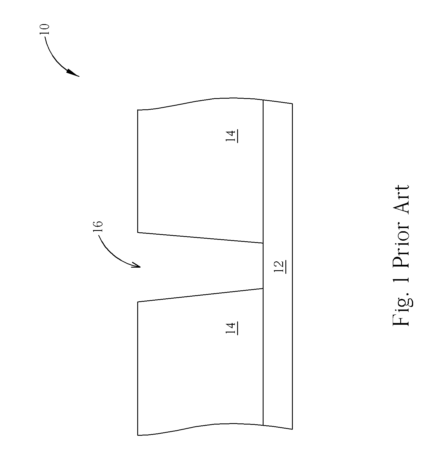
However, the halogen lamp treatment is not a forceful degas process, so it does not degas the dielectric layer 14 effectively.

Method used


Image

  • Method of fabricating a semiconductor device
  • Method of fabricating a semiconductor device
  • Method of fabricating a semiconductor device

Examples


Embodiment Construction

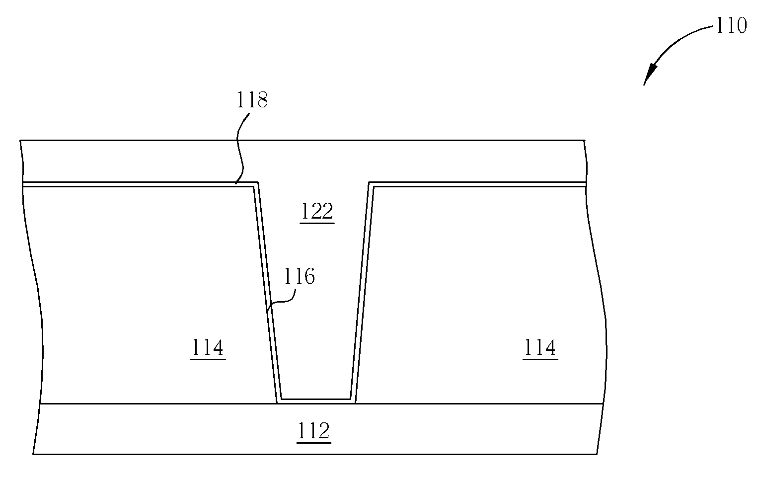
[0021]Please refer to FIGS. 6 through 10. FIGS. 6 through 10 are schematic diagrams illustrating a method of manufacturing a conducting plug in accordance with a first preferred embodiment of the present invention, where like number numerals designate similar or the same parts, regions or elements. The formed conducting plug in this preferred embodiment can be a contact plug or a via plug. It is to be understood that the drawings are not drawn to scale and are only for illustration purposes. In addition, some lithographic and etching processes relating to the present invention method are known in the art and thus not explicitly shown in the drawings.

[0022]As shown in FIG. 6, a semiconductor wafer 110 is provided first. The semiconductor wafer 110 includes a semiconductor substrate 112, an etching stop layer 126 covering the semiconductor substrate 112, a dielectric layer 114 positioned on the etching stop layer 126, and a patterned hard mask 128 positioned on the dielectric layer 11...


PUM


Abstract

A method of fabricating a semiconductor device is provided. First, a semiconductor substrate and a dielectric layer positioned on the semiconductor substrate are prepared. Subsequently, the dielectric layer is etched to form a hole structure in the dielectric layer. Afterward, a degas process is performed. An ultraviolet (UV) treatment is carried out to the semiconductor substrate in the degas process so as to expel at least a gas contained in the dielectric layer. Next, a barrier layer is formed on the sidewall and on the bottom of the hole structure. Furthermore, the hole structure is filled with a conductive material. Since the UV treatment can degas the dielectric layer efficiently, the formed semiconductor device can have a fine and stable structure.

Description

BACKGROUND OF THE INVENTION[0001]1. Field of the Invention[0002]The present invention relates to a method of fabricating a semiconductor device, and more particularly, to a method of fabricating a semiconductor device by utilizing a degas process.[0003]2. Description of the Prior Art[0004]For today's narrower line width and faster production speeds, damascene structures are formed in a dielectric material by means of a physical vapor deposition (PVD) metal process so as to fabricate metal interconnects of integrated circuits. Generally speaking, the PVD process utilizes inert gas, such as argon, to bombard a target material in high speed for sputtering atoms from the target. Thereafter, the sputtered atoms of the target material, such as aluminum, titanium, or alloy thereof, evenly deposit on the surface of a wafer. The reaction chamber provides a vacuum environment with high temperature, and thus the metal atoms deposited on the wafer become crystallized grains so as to form a meta...

Claims


Application Information

Patent Timeline
Patent Type & Authority Applications(United States)
IPC IPC(8): H01L21/44
CPCH01L21/02063H01L21/3105H01L21/76814H01L21/76825
Inventor LIN, TSANG-JUNGCHUANG, FONG-LUNG
Owner UNITED MICROELECTRONICS CORP
Why Eureka
Try Eureka