Magnetic nanoparticle therapies

a technology of magnetic nanoparticles and nanoparticles, applied in the field of fluorescent nanoparticles, can solve the problems of many anatomical spaces and tissues, inaccessible and viewable, and expensive and time-consuming imaging equipment use,

Inactive Publication Date: 2008-10-16
ETHICON ENDO SURGERY INC
View PDF80 Cites 63 Cited by
  • Summary
  • Abstract
  • Description
  • Claims
  • Application Information

AI Technical Summary

Benefits of technology

[0009]In yet another embodiment, an endoscopic system is provided and includes an endoscope eyepiece having a viewing lumen formed therethrough between proximal and distal ends thereof, and an adaptor adapted to removably mate to the endoscope eyepiece and adapted to retain a filter therein such that the filter is in alignment with the viewing lumen formed in the endoscope eyepiece to thereby filter light through the viewing lumen. The adaptor can include a viewing lumen extending therethrough and adapted to be aligned with the viewing lumen in the endoscope eyepiece when the adaptor is mated to the endoscope eyepiece. In an exemplary embodiment, the adaptor can be an eyepiece extension member having the viewing lumen formed therein, and a mating element adapted to mate to the eyepiece extension to engage a portion of the endoscope eyepiece therebetween. A filter can optionally be removably or fixedly disposed within the adaptor. In an exemplary embodiment, the filter is adapted to transmit light in the fluorescent waveband. In other aspects the adaptor can include a filter cartridge removably disposed therein and adapted to retain a filter therein.

Problems solved by technology

Many anatomical spaces and tissues, however, are not easily accessible and viewable.
Moreover, the use of imaging equipment can be expensive and time consuming, and their application is often limited.
Despite many successful applications, conventional optical labels have many drawbacks.
For example, conventional optical labels are generally toxic to living cells and tissues comprised of living cells.
Additionally, conventional optical labels such as fluorescent dyes generally suffer from short-lived fluorescence because the dyes undergo photo bleaching after minutes of exposure to an excitation light source.
This renders them unsuitable for optical imaging that requires extended time period of monitoring.
Moreover, conventional optical labels are sensitive to environmental changes such as pH and oxygen concentration.
Another drawback of conventional optical labels is that typically the excitation spectra of such labels are quite narrow, while the emission spectra of such labels is relatively broad, resulting in overlapping emission spectra.
Additionally, fluorescent labels are generally inefficient at converting the excitation light to the emission wavelength, and the resulting signal can be very weak.

Method used


Image

  • Magnetic nanoparticle therapies
  • Magnetic nanoparticle therapies
  • Magnetic nanoparticle therapies

Examples


Embodiment Construction

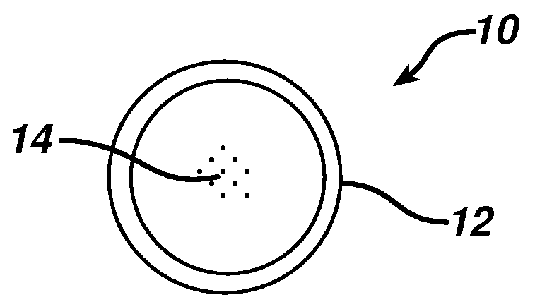
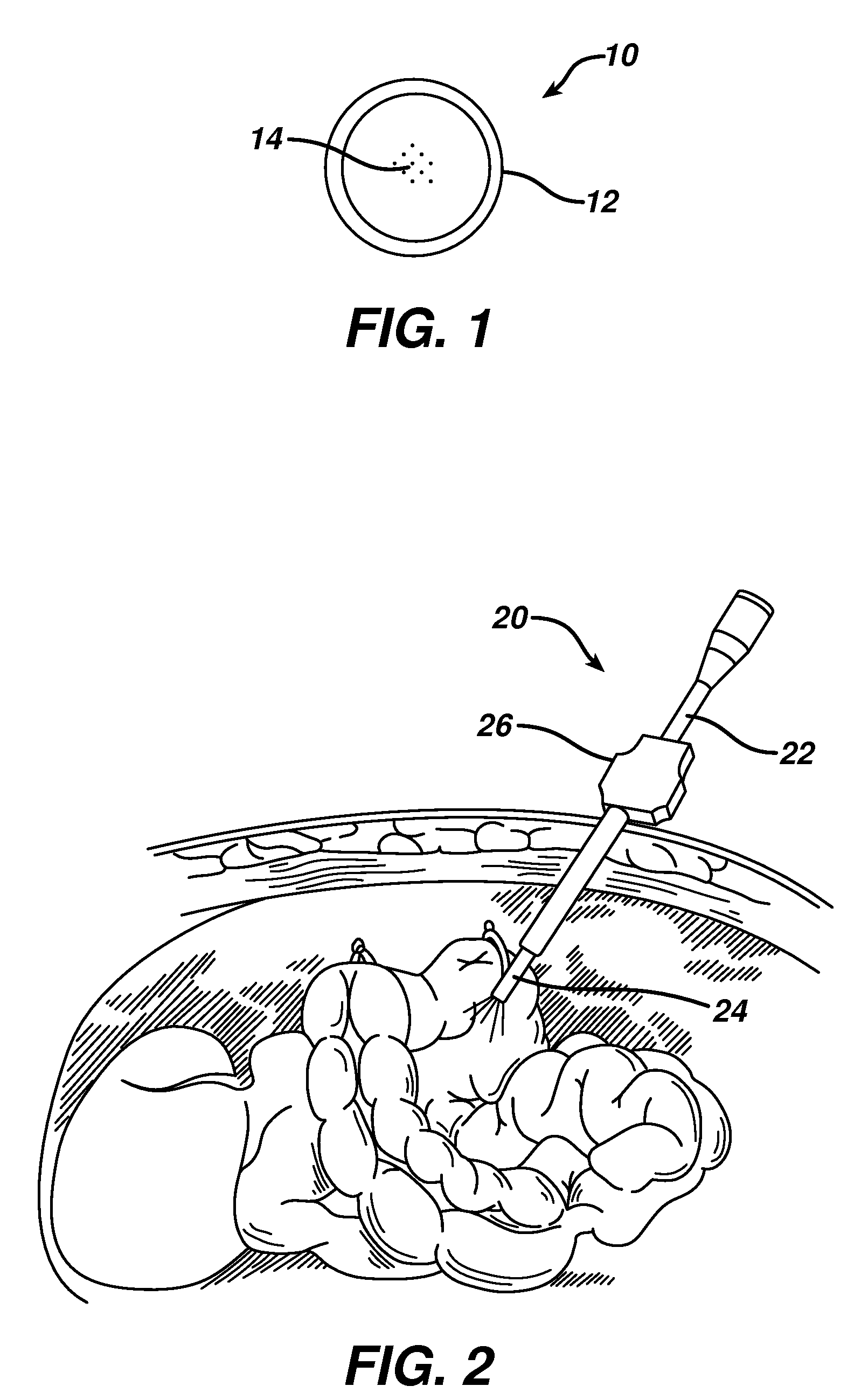
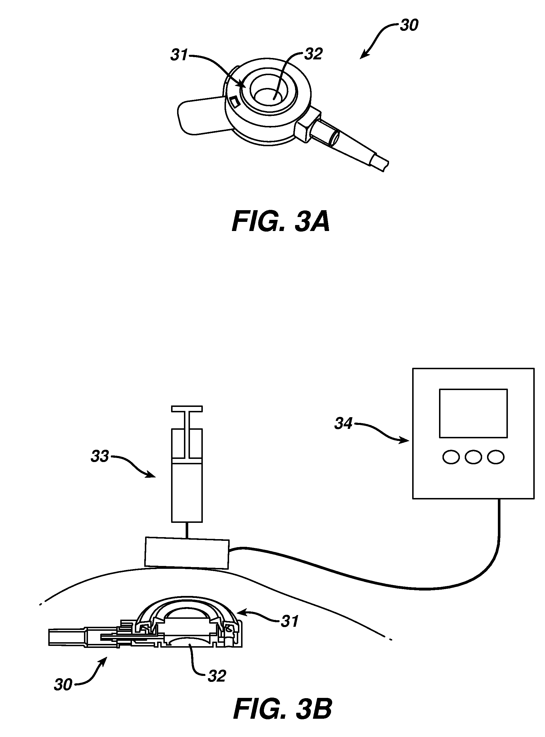
[0026]Certain exemplary embodiments will now be described to provide an overall understanding of the principles of the structure, function, manufacture, and use of the devices and methods disclosed herein. One or more examples of these embodiments are illustrated in the accompanying drawings. Those skilled in the art will understand that the devices and methods specifically described herein and illustrated in the accompanying drawings are non-limiting exemplary embodiments and that the scope of the present invention is defined solely by the claims. The features illustrated or described in connection with one exemplary embodiment may be combined with the features of other embodiments. Such modifications and variations are intended to be included within the scope of the present invention.

[0027]The present invention generally provides various compositions, methods, and devices for using fluorescent nanoparticles in various medical applications. In certain exemplary embodiment, the fluo...


PUM


Abstract

Various compositions, methods, and devices are provided that use fluorescent nanoparticles, which can function as markers, indicators, and light sources. The fluorescent nanoparticles can be formed from a fluorophore core surrounded by a biocompatible shell, such as a silica shell. In one embodiment, the fluorescent nanoparticles can be delivered to tissue to mark the tissue, enable identification and location of the tissue, and / or illuminate an area surrounding the tissue. In another embodiment, the fluorescent nanoparticles can be used on a device or implant to locate the device or implant in the body, indicate an orientation of the device or implant, and / or illuminate an area surrounding the device or implant. The fluorescent nanoparticles can also be used to provide a therapeutic effect.

Description

CROSS REFERENCE TO RELATED APPLICATIONS[0001]This application claims priority to U.S. Provisional Patent Application No. 60 / 911,546 filed on Apr. 13, 2007 and entitled “Fluorescent Nanoparticle Compositions, Methods, and Devices,” which is hereby incorporated by reference in its entirety.FIELD OF THE INVENTION[0002]The present invention relates to fluorescent nanoparticles, and in particular to various compositions, methods, and devices that use fluorescent nanoparticles.BACKGROUND OF THE INVENTION[0003]Illuminating light incident on tissue is transmitted through, scattered by, absorbed, or reflected by that tissue. At certain wavelengths, after absorbing the illuminating light, tissue can re-emit light energy at a different wavelength (autofluorescence). If a substance is introduced into the tissue or is present between tissue layers, or in lumens, it can fluoresce after absorbing incident light as well. Detecting devices can be placed in relationship to the tissue to image light t...

Claims


Application Information

Patent Timeline
Patent Type & Authority Applications(United States)
IPC IPC(8): A61N2/00
CPCA61B1/043A61B1/3132A61B5/0071A61B5/0075A61B5/0084A61B5/415A61B5/418A61K41/0052A61K49/0017A61K49/0093
Inventor VOEGELE, JAMES W.GILL, ROBERT P.
Owner ETHICON ENDO SURGERY INC
Why Eureka
Try Eureka