
Method and Apparatus for Optimizing Current Consumption of Amplifiers with Power Control

a power amplifier and current consumption technology, applied in the direction of transmission, transmission monitoring, modulation, etc., can solve the problems of reducing efficiency, reducing efficiency, and withdrawing from saturation level, so as to increase the efficiency of an rf power amplifier (pa). , the effect of reducing current consumption

Active Publication Date: 2008-10-23
QUALCOMM INC
View PDF17 Cites 7 Cited by
  • Summary
  • Abstract
  • Description
  • Claims
  • Application Information

AI Technical Summary

Benefits of technology

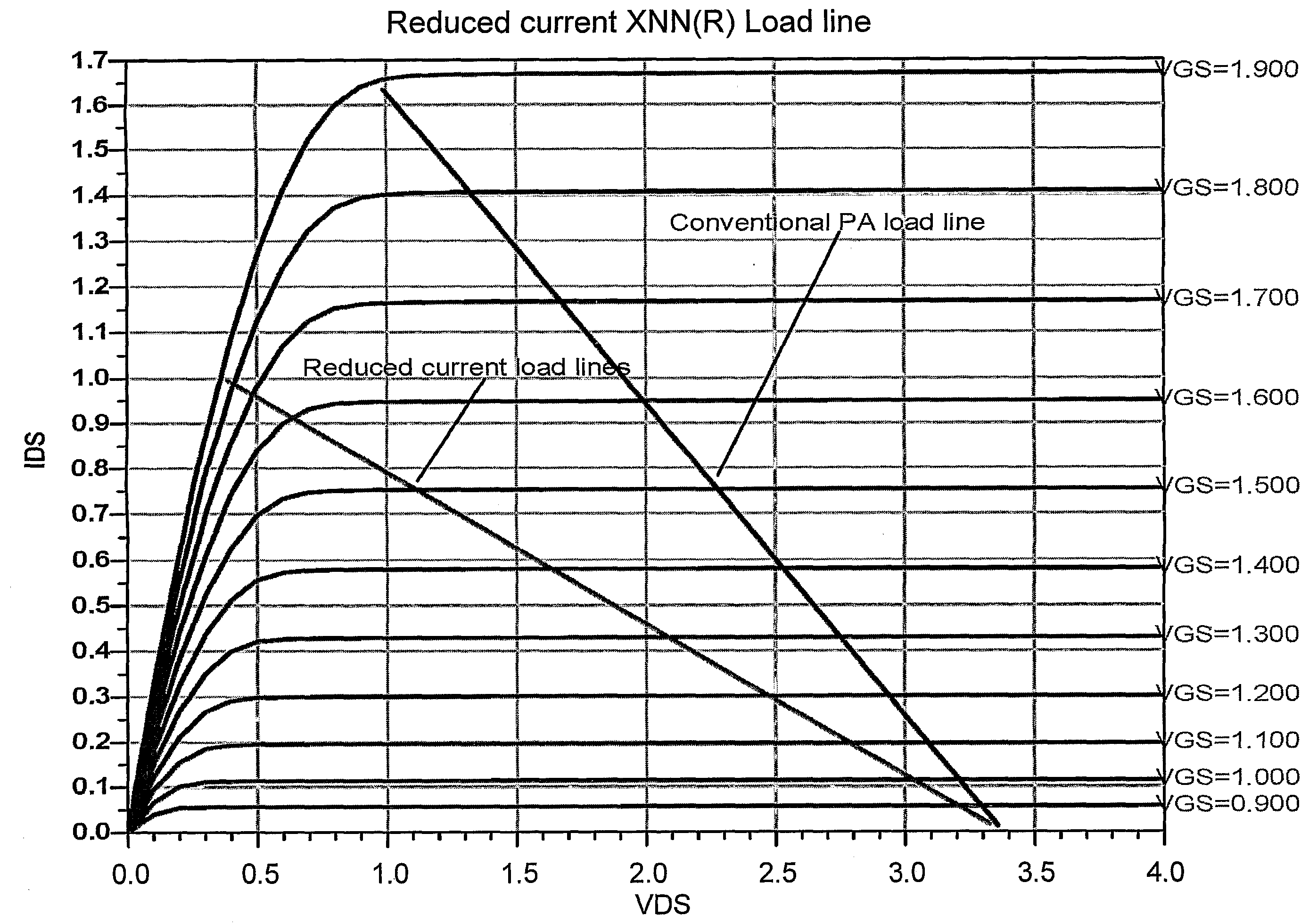
[0010]The present invention is directed to a method for reducing the current consumption and increasing the efficiency of an RF power amplifier (PA), according to which the load, connected to the output stage of the PA, tuned dynamically or statically for each level of the desired output power. By doing so, the output impedance of the output stage is essentially matched, such that the dynamic RF load line has a slope that corresponds to the impedance required to provide this level. Whenever a smaller output power is desired in response to reduction in the input signal to the amplifier, the load is further tuned, such that the dynamic or static RF load line has a slope that causes the power amplifier to essentially remain in saturation at the smaller output power.
[0013]The present invention is directed to an apparatus for reducing the current consumption and increasing the efficiency of an RF power amplifier (PA), that comprises a matching circuitry for dynamically or statically tuning the load, connected to the output stage of the PA, to essentially match the output impedance of the output stage for each level of the desired output power, such that the dynamic RF load line has a slope that causes the power amplifier to essentially remain in saturation at the level.

Problems solved by technology

Withdrawal from saturation level will reduce efficiency.
According to conventional solutions, the power stage is designed to handle the highest expected power, leading to lower efficiency at lower output power levels due to high quiescent currents.
Still, the methods described above have not provided satisfactory solutions to the problem of improving the efficiency of power amplifiers operated under large peak-to-average ratio input signals.

Method used


Image

  • Method and Apparatus for Optimizing Current Consumption of Amplifiers with Power Control
  • Method and Apparatus for Optimizing Current Consumption of Amplifiers with Power Control
  • Method and Apparatus for Optimizing Current Consumption of Amplifiers with Power Control

Examples


example 1

Adaptive Load Line Changing for Power Controlled System

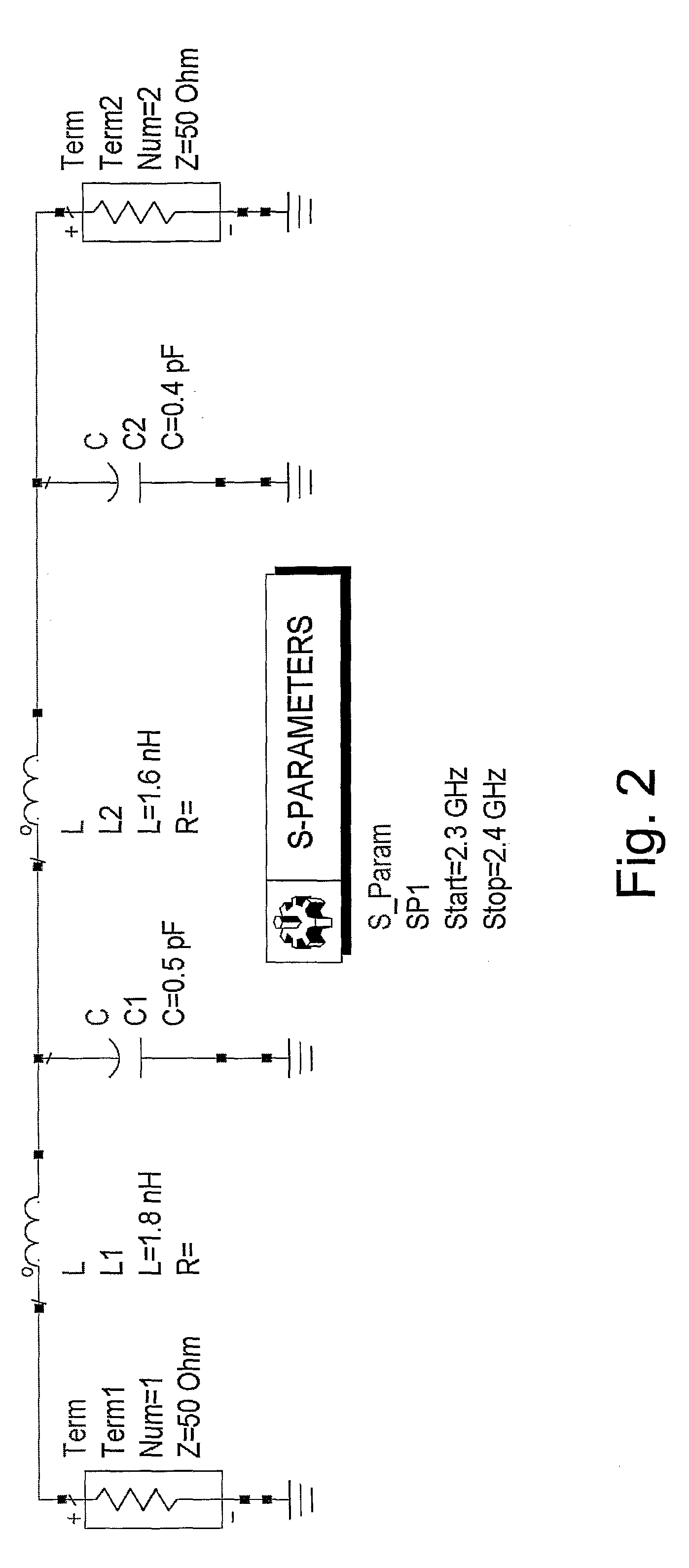
[0026]Most of the advanced power amplifiers have internal pre-matching and no external matching is required while using a 50Ω load. For this example, it is assumed that the amplifier used is pre-matched to a 50Ω load. Increasing the output load line impedance can be done using classical matching techniques. FIG. 2 hereinbelow is an example for such matching circuit and FIG. 3 hereinbelow is its simulation results for 75Ω load impedance.

[0027]The load line curve can be adaptively changed by simply tuning the parallel capacitors shown in the matching circuit FIG. 2. Load lines in the range of 50-85Ω have been tested.

[0028]As an example, a design of a power controlled power amplifier for a Global System for Mobile Communications (GSM) mobile phone working according to the 3GPP GSM standard TS 45.005 is illustrated. Control of nominal output power is done in 2 dB steps. The maximum output power levels for handset mobile stations cla...

example 2

Adaptable MIMO Arrays

[0030]For a specific MIMO system with up to four amplifier paths, the total power has been designed to stay constant for all operational modes. That means that for the case where only one amplifier operates, it should work at maximum power. If more paths are operating, the power of each of them is reduced by a factor of the number of paths. For optimal operation, the first amplifier was designed to work at maximal power level, with adaptive load line control, similar to the previous example. The others were designed to work with lower power level. The system efficiency remains high for all system modes.

[0031]For a MIMO W-LAN system working according to the IEEE standard 802.11n with up to four transmit paths, the total output power is limited to 100 mW (20 dBm), due to the to total output power limitations for systems operating in the unlicensed frequency bands. If for example, we have four Power Amplifiers (PAs) that comply with the standard mask requirements a...


PUM


Abstract

Apparatus and method for reducing the current consumption and increasing the efficiency of an RF power amplifier (PA), according to which the load, connected to the output stage of the PA, tuned dynamically or statically for each level of the desired output power. By doing so, the output impedance of the output stage is essentially matched, such that the dynamic RF load line has a slope that corresponds to the impedance required to provide this level. Whenever a smaller output power is desired in response to reduction in the input signal to the amplifier, the load is further tuned, such that the dynamic or static RF load line has a slope that causes the power amplifier to essentially remain in saturation at the smaller output power.

Description

FIELD OF THE INVENTION[0001]The present invention relates to the field of high efficiency power amplifiers. More particularly, the invention relates to a matching technique for reducing current consumption of RF power amplifiers when no change in output power is required.BACKGROUND OF THE INVENTION[0002]RF amplifiers normally achieve their maximum efficiency while being at saturation level. In many wireless applications, controlling output power as a function of receiving level is required. Withdrawal from saturation level will reduce efficiency. According to conventional solutions, the power stage is designed to handle the highest expected power, leading to lower efficiency at lower output power levels due to high quiescent currents.[0003]One of the conventional ways to eliminate this problem is to control the DC supply of the power amplifier as a function of the power level. This solution is described for example, in U.S. Pat. No. 6,437,641, which discloses circuitry for dynamical...

Claims


Application Information

Patent Timeline
IPC IPC(8): H03F3/60
CPCH03F1/0205H03F1/56H03F3/191H03F2200/387H03F2200/391H03G1/0064H03F3/211H03F3/245
Inventor ELIA, AVNER
Owner QUALCOMM INC
Learn More