Solid electrolytic capacitor

a technology of electrolytic capacitor and solid electrolytic capacitor, which is applied in the direction of liquid electrolytic capacitor, fixed capacitor, fixed capacitor details, etc., can solve the problem that two techniques cannot be simply combined, and achieve the effect of reducing esl, reducing esl, and increasing esr

Inactive Publication Date: 2008-10-23
TOKIN CORP
View PDF5 Cites 9 Cited by
  • Summary
  • Abstract
  • Description
  • Claims
  • Application Information

AI Technical Summary

Benefits of technology

[0018]The second subject is the presence of the plurality of through holes formed in the thickness direction in Patent Document 1. In Patent Document 1, it is configured that the plurality of through holes are arranged in the lattice point pattern and the inner side of each through hole is used as the electrode terminal of the anode portion while the outer side thereof is used as the electrode terminal of the cathode portion, thereby shortening the wiring distances. However, in this case, it is necessary to provide the through holes in the cathode portions on both sides as many as the number of external anode terminals formed at an electrode surface of the solid electrolytic capacitor and the area of the cathode portions is reduced corresponding to the regions on the inner side of the through holes. Since the reduction in area of the cathode portions directly leads to a reduction in capacitance of the solid electrolytic capacitor, it is necessary to optimize the positions and area of the through holes so as to minimize the reduction in area of the cathode portions.
[0054]According to this invention, it is possible to achieve a reduction in ESL in a solid electrolytic capacitor using a conductive polymer as an electrolyte, wherein anodized films are formed at both surfaces of a flat plate-shaped anode body, a solid electrolyte layer and a cathode layer are further formed in the order named on each of the anodized films, and further, an anode lead portion is provided at the peripheries of four sides of a rectangular cathode portion comprising the solid electrolyte layer and the cathode layer, with an insulator layer interposed between the cathode portion and the anode lead portion. Means therefor is such that an opening is provided at least one of four corners of the insulator layer or the anode lead portion and a conductive portion in the form of a conductive paste or a metal foil is provided in the opening at its inner wall surface for electrical connection between the cathode portions provided on both sides of the capacitor, thereby establishing electrical connection between the cathode portions on both sides. Further, by controlling the size and shape of the opening so that the ratio of a length of a region removed by providing the opening is set to 25% or less with respect to the total length of the peripheries of the cathode portion, it is possible to realize a reduction in ESL without causing a large increase in ESR or a large reduction in capacitance in the solid electrolytic capacitor.

Problems solved by technology

However, these two techniques cannot be simply combined together for the following reasons and an approach is necessary for solving these technical subjects.

Method used


Image

  • Solid electrolytic capacitor
  • Solid electrolytic capacitor
  • Solid electrolytic capacitor

Examples


example 1

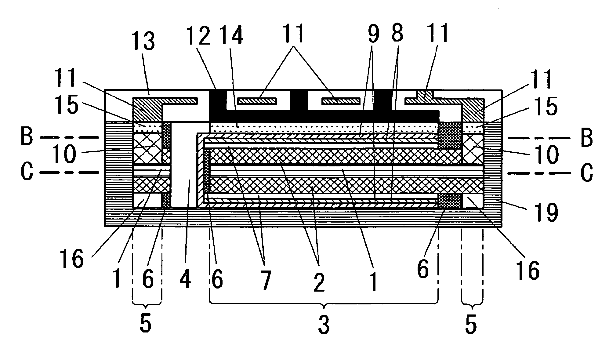
[0092]The solid electrolytic capacitor according to the foregoing first embodiment was fabricated by the following method and its electrical characteristics were measured. At first, a foil-like aluminum base was formed porous and, then, anodized films were formed at both surfaces thereof. Herein, the foil-like aluminum base is commercialized as a material for an aluminum electrolytic capacitor, wherein the nominal anodization voltage when forming anodized films at its surfaces is 3V, the capacitance per unit area (cm2) is 220 μF, and the thickness is 70 μm. This foil-like aluminum base was cut into a square shape with a width of 4.5 mm and a length of 4.5 mm and it was determined to form a cathode portion in a square region with a width of 3.2 mm and a length of 3.2 mm in the center of the aluminum base on each side thereof. Then, openings in the form of circular through holes were formed in the aluminum base in its thickness direction, using as the centers of circles the positions ...

example 2

[0097]The solid electrolytic capacitor according to the foregoing second embodiment was fabricated and its electrical characteristics were measured. The size and shape of the fabricated solid electrolytic capacitor and the fabrication sequence were substantially the same as those in Example 1. However, circular openings formed in an aluminum base in its thickness direction using as the centers of circles the positions of the four vertices of a 3.2 mm square region determined for a cathode portion were through holes each having a diameter of 0.8 mm. By setting the diameter of each opening to be about three times greater than that in Example 1, the ratio of the openings was increased to 25%. The number of solid electrolytic capacitors fabricated and used in the measurement was 30 equal to that in Example 1. Measurement items and a measurement method were also the same as those in Example 1. The average values of the respective characteristics of the 30 solid electrolytic capacitors ar...

example 3

[0098]The solid electrolytic capacitor according to the foregoing third embodiment was fabricated and its electrical characteristics were measured. The size and shape of the fabricated solid electrolytic capacitor and the fabrication sequence were substantially the same as those in Example 1. However, instead of the circular openings, square openings each having a width of 0.35 mm and a length of 0.35 mm were formed at four corners of an aluminum base, in its thickness direction, having a width of 4.5 mm and a length of 4.5 mm. A region of each opening was located only at an anode portion on the aluminum base and did not reach a cathode portion or an insulator layer. Therefore, there was no region occupied by the openings in a region where the anode portion and the cathode portion faced each other and thus the ratio of the openings was 0%.

[0099]The openings and the cathode portions were isolated from each other by the insulator layers, but when forming metal layers each having a thi...


PUM

PropertyMeasurementUnit
thicknessaaaaaaaaaa
capacitanceaaaaaaaaaa
lengthaaaaaaaaaa

Abstract

Anodized films are formed at both surfaces of an aluminum base and, at the center portion on each side of the aluminum base, a solid electrolyte layer of a conductive polymer, a graphite layer, and a metal layer are stacked in the order, thereby forming a rectangular cathode portion. An insulator layer is formed at the peripheries of four sides of the cathode portion and, further, an anode lead frame is provided at the peripheries of four sides of the upper insulator layer, thereby forming an anode portion. Openings are formed at four corners of the insulator layer or the anode portion, thereby establishing electrical connection between the cathode portions on both sides of the aluminum base. By setting the ratio of a total region, occupied by the openings, of the cathode portion to 25% or less, the ESL of a capacitor can be suppressed low even when the openings are provided.

Description

[0001]This application is based upon and claims the benefit of priority from Japanese patent application No. 2007-110317, filed on Apr. 19, 2007, the disclosure of which is incorporated herein in its entirety by reference.BACKGROUND OF THE INVENTION[0002]This invention relates to a solid electrolytic capacitor using a flat plate-shaped valve action metal and, in particular, relates to a solid electrolytic capacitor with a large capacitance and a low ESL (Equivalent Series Inductance), using a conductive polymer as an electrolyte.[0003]In recent years, reduction in size and increase in functionality of digital devices have been advanced. Accordingly, power supplies to be connected to the devices have also been required for adaptation to driving at high frequencies. Following it, noise countermeasures and smoothing of power supply voltages have become necessary. Thus, the roles of electrolytic capacitors in electronic circuits have been getting important. In these circumstances, there...

Claims


Application Information

Patent Timeline
Patent Type & Authority Applications(United States)
IPC IPC(8): H01G9/15
CPCH01G9/012H01G9/14H01G9/15H01G9/028
Inventor YOSHIDA, YUJIYOSHIDA, KATSUHIROKASUGA, TAKEOTAKAHASHI, MASANORISAITO, TAKESHISAKATA, KOJI
Owner TOKIN CORP
Why Eureka
Try Eureka