Tape-Style Flexible Circuit Board, and Manufacturing Method and Manufacturing Apparatus for the Same

a flexible circuit board and tape-style technology, applied in the direction of printed circuit aspects, transportation and packaging, chemistry apparatus and processes, etc., can solve the problems of reducing the range to which the above-described proposal is applied, the loss of connection portions approaching the limit, and the inability to meet the requirements of precision, etc., to reduce the loss of connection portions, and reduce the loss of flexible circuit boards

Inactive Publication Date: 2008-10-23
TORAY IND INC
View PDF3 Cites 58 Cited by
  • Summary
  • Abstract
  • Description
  • Claims
  • Application Information

AI Technical Summary

Benefits of technology

[0013]According to the present invention, the loss in the connection portion can be reduced while keeping the strength of connection high when a number of sheet-style flexible circuit boards are connected to each other so as to form a tape-style flexible circuit board. In addition to the reduction of the loss of flexible circuit boards for the connection, the loss in time for recognizing and feeding the connection portion can be reduced when an electronic part is bonded to the tape-style flexible circuit board. In particular, according to the manufacturing method and the manufacturing apparatus of the present invention, a number of flexible circuit boards are connected to each other on reinforcing plates, and therefore, the flexible circuit boards are easy to handle, and in addition, a high precision of location can be secured so that two flexible circuit boards can be connected to each other without fail.

Problems solved by technology

However, the progress of miniaturization is approaching the limit.
Though there are techniques to further miniaturize the line width and the space width, the precision of the locations, which is the latter index, relates to the positioning between the electrode pads of electronic parts and the circuit pattern when electronic parts, such as IC's, are bonded to a circuit board, and thus, it is becoming harder to cope with the required precision as the number of pins of IC's increases.
Accordingly, a problem arises where the range to which the above described proposal is applied is limited.
Therefore, though there is a possibility that sheet-style flexible circuit boards are connected to form a tape-style flexible circuit board so that the range of application can be expanded, it is difficult to convey and position flexible circuit boards in sheet form having a thickness of, for example, several tens of μm in a state where they are not laminated onto a reinforcing plate, and therefore, the automation of the connection step is difficult, and furthermore, the automation of the subsequent process of the tape-style flexible circuit board is also difficult.
In accordance with this method, however, a problem arises where the portions of the flexible circuit boards which are the front or the back of the connection portion in addition to the connection portions end up being wasted.
When the portions of the flexible circuit boards which are the front or the back of the connection portion cannot be used as described above, however, the tape-style flexible circuit board is fed without bonding an IC to the circuit patterns on the front or the back of the connection portion.
That is to say, time loss occurs due to feeding without bonding in the step of bonding an IC to the tape-style flexible circuit board.
In accordance with this method, however, the portions of the flexible circuit boards in the connection portion end up being wasted in the same manner as in the above described method.
Furthermore, connections as described above are required in the case where defects collectively occur in the group of circuit patterns which are formed on the tape-style flexible circuit board.
Furthermore, in accordance with this method, such a thermoplastic film is used, and therefore, it is difficult to implement the method in the case where the method includes a heating step, such as resin molding or solder reflow, in the subsequent step.
That is to say, it is difficult to utilize both the ease of caulking due to a change in form through heating and the resistance to heat in the subsequent step.

Method used


Image

  • Tape-Style Flexible Circuit Board, and Manufacturing Method and Manufacturing Apparatus for the Same
  • Tape-Style Flexible Circuit Board, and Manufacturing Method and Manufacturing Apparatus for the Same
  • Tape-Style Flexible Circuit Board, and Manufacturing Method and Manufacturing Apparatus for the Same

Examples


example 1

[0233]A tape-style polyimide film (“Kapton” 150EN (trade name), made by Dupont-Toray Co., Ltd.) having a thickness of 25 μm was prepared as a base film which formed a flexible circuit board. An alloy layer of chromium and nickel, of which the weight ratio was chromium:nickel=5:95 and a thickness of 15 nm, and a copper layer having a thickness of 150 nm were layered on the polyimide film in this order using a sputtering apparatus for reel-to-reel processing on a tape-style circuit board.

[0234]A removable organic material was applied to sodalime glasses (300 mm×350 mm having a thickness of 1.1 mm) which are reinforcing plates using a die coater, and was dried at 80° C. for two minutes. As the removable organic material, a mixture of a ultraviolet ray curing type adhesive “SK Dyne” SW-22 (made by Soken Chemical and Engineering Co., Ltd.) and an curing agent L45 (made by Soken Chemical and Engineering Co., Ltd.) at a weight ratio of 100:3 was used. The thickness of the removable organic...

example 2

[0247]A tape-style flexible circuit board was fabricated in the same manner as in Example 1, except that a resin was applied with a length of 0.4 mm in the direction of conveyance throughout the entire width in the direction perpendicular to the direction of conveyance between spaces for conveyance.

[0248]The strength of connection was measured in the same manner as in Example 1 and was found to be 13 N, which was strength sufficient for conveyance in the post processing.

example 3

[0249]A tape-style flexible circuit board was fabricated in the same manner as in Example 1, except that the temperature of the head of the heat and pressure application means 416 was 200° C.

[0250]The strength for connection was measured in the same manner as in Example 1 and was found to be 4.7 N, which was strength that could be used in the post processing. However, there was a concern that the margin was slightly insufficient in the case where a force for intermittent feeding was applied.


PUM

PropertyMeasurementUnit
lengthaaaaaaaaaa
lengthaaaaaaaaaa
flatnessaaaaaaaaaa

Abstract

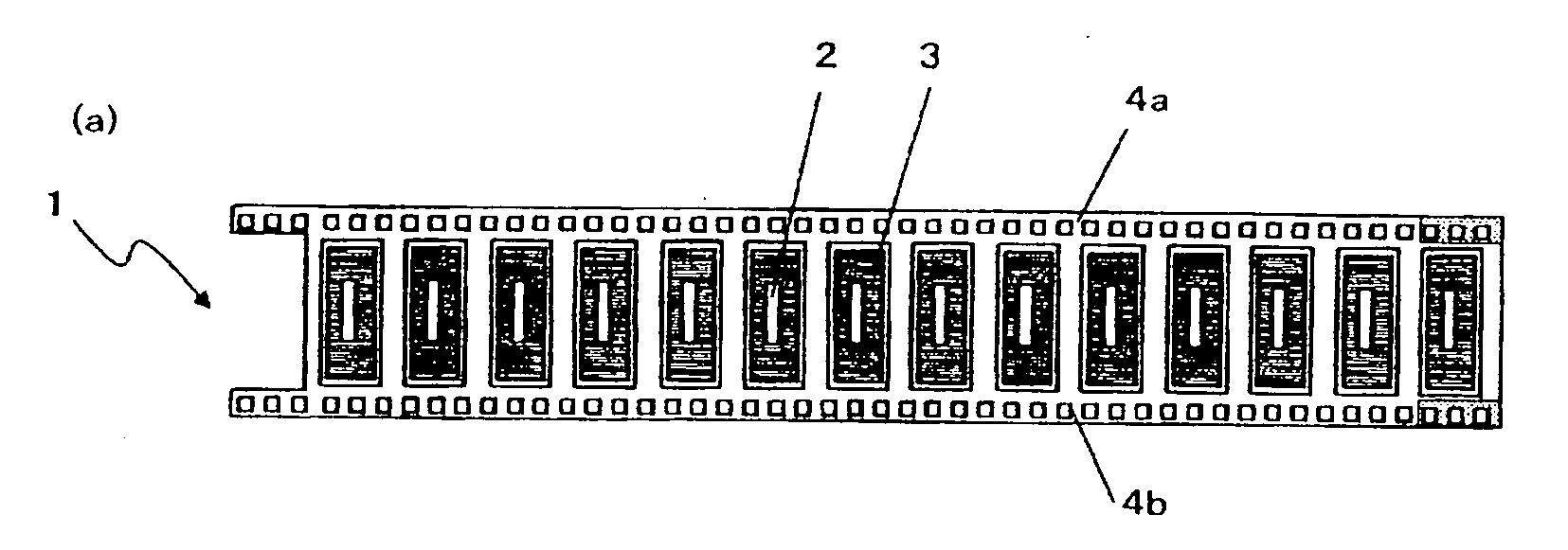
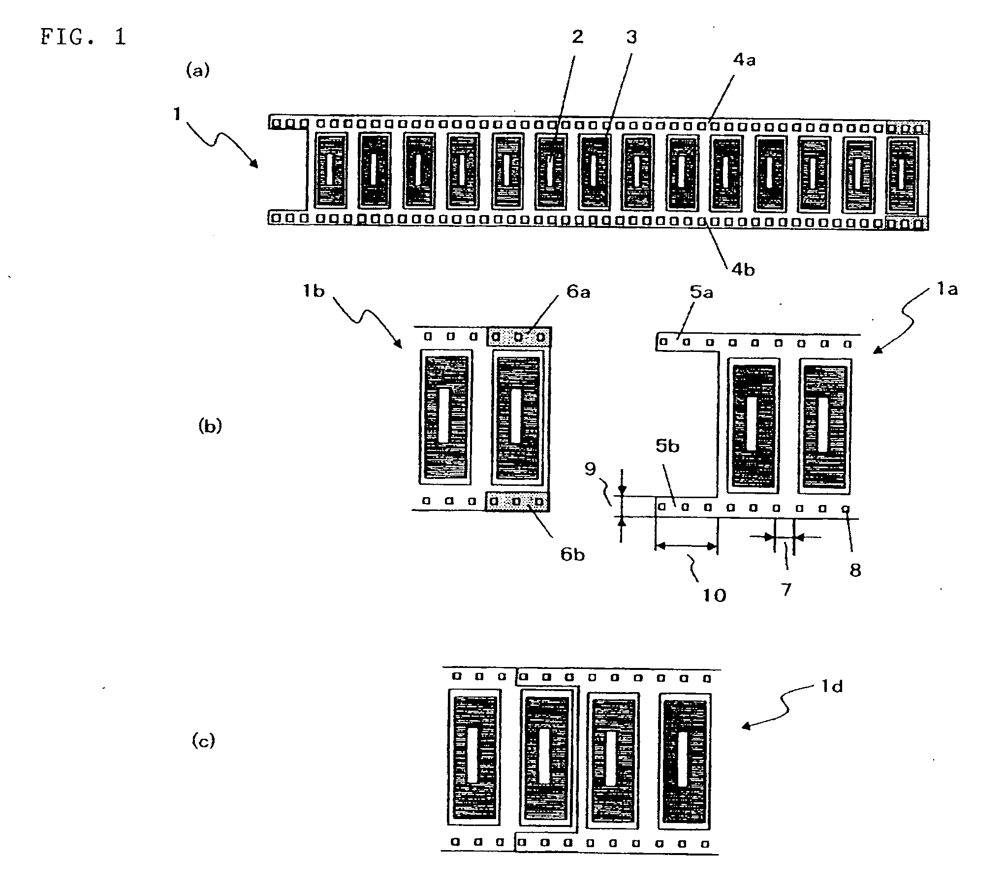
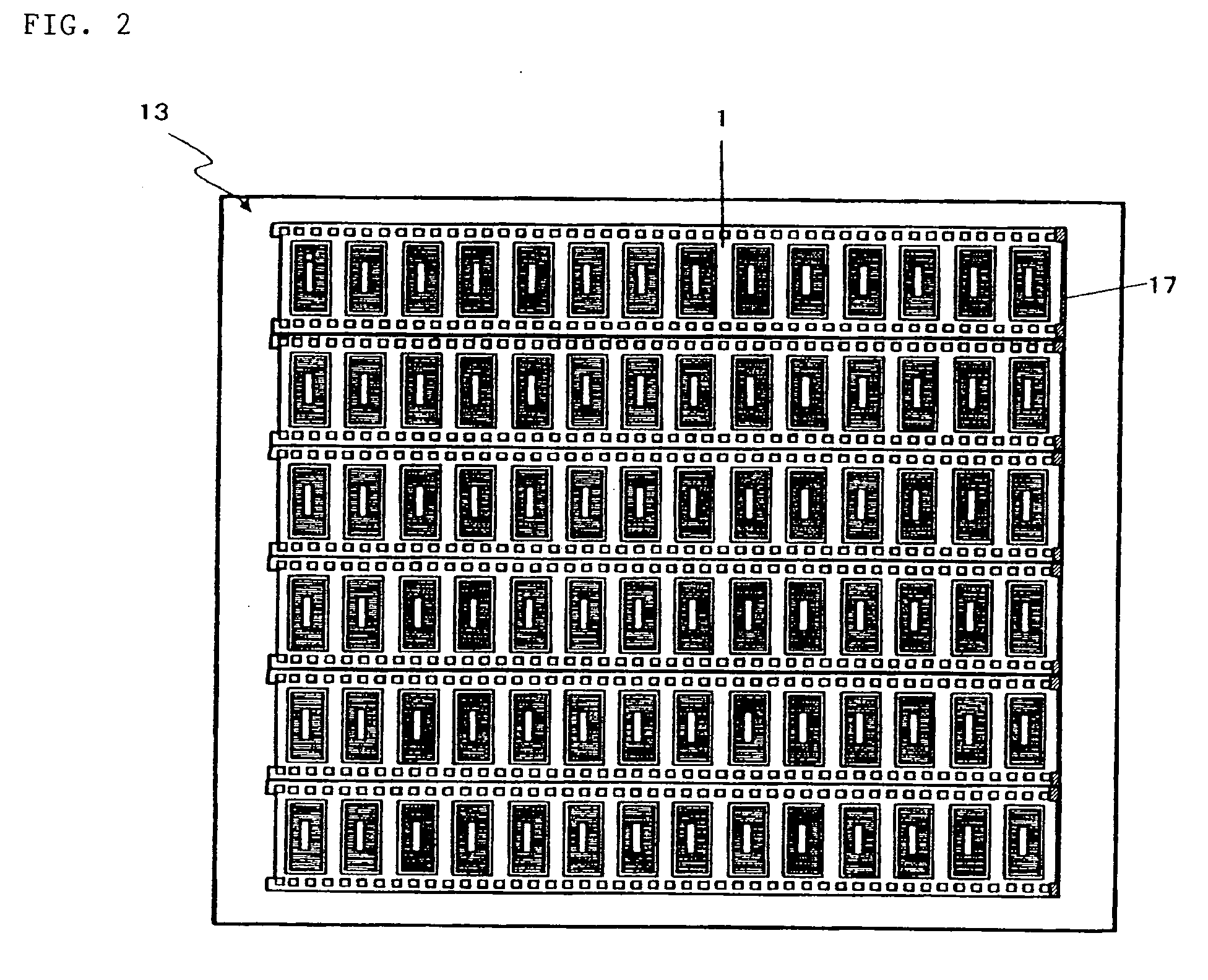
When a number of flexible circuit boards where a circuit pattern is formed on at least one surface are connected to each other so as to form a tape-style flexible circuit board, a space for conveyance is provided in the pairs of end portions facing each other of the flexible circuit boards, at least a portion of the space for conveyance protrudes in the direction parallel to the direction of conveyance of the flexible circuit boards, and the protruding space for conveyance overlaps and is fixed to a space for conveyance of an adjacent flexible circuit board.

Description

TECHNICAL FIELD[0001]The present invention relates to a tape-style flexible circuit board using a flexible film which is appropriate as a circuit board having a highly precise circuit pattern, and a manufacturing method and a manufacturing apparatus for the same.BACKGROUND ART[0002]Together with the reduction in weight and the miniaturization of electronic products, an increase in the precision of patterning of printed circuit boards has been required. Flexible circuit boards can be bent, making three-dimensional wiring possible, and therefore, appropriate for the miniaturization of electronic products, and thus, demands have been expanded. In accordance with a COF (chip on flex) technology which is used for connecting an IC to a liquid crystal display panel, a tape-style flexible circuit board having a relatively narrow width and made of polyimide is processed. As a result, the finest pattern for a resin substrate can be gained. However, the progress of miniaturization is approachi...

Claims


Application Information

Patent Timeline
Patent Type & Authority Applications(United States)
IPC IPC(8): H05K1/00H05K3/00B32B37/14
CPCH05K1/0393H05K3/0097H05K2201/10598Y10T156/17H05K2203/0264H05K2203/1545H05K2203/016B65H37/04
Inventor TANIMURA, YASUAKIAKAMATSU, TAKAYOSHIOKUYAMA, FUTOSHIKUROKI, NOBUYUKI
Owner TORAY IND INC
Why Eureka
Try Eureka