Cell Sorting System and Methods

a sorting system and cell technology, applied in the field of cell sorting system and methods, can solve the problems of inability to sterilize, and inability to perform sorting,

Inactive Publication Date: 2008-10-23
PROGENITY INC
View PDF51 Cites 182 Cited by
  • Summary
  • Abstract
  • Description
  • Claims
  • Application Information

AI Technical Summary

Benefits of technology

[0012]In yet another embodiment, a fluidic switch may be utilized. Preferably, a pneumatic based fluidic switch may be utilized. In another embodiment, a microfluidic chip design for cell sorter uses pneumatic pressure modulation. A single side channel for flow switching or cell sorting may be used in microfluidic devices. The described channel geometry provides for efficient pneumatic flow switching in microfluidic devices. In yet another aspect, a coupling of two switching valves on a single side channel minimizes pneumatic switching response time. In yet another aspect, a cartridge holder is provided for pneumatic control of microfluidic chips.

Problems solved by technology

These instruments are capable of very fast, multiparameter analysis and sorting but generally require large sample volumes, a trained operator for operation and maintenance, and are difficult to sterilize.
However, below 100,000 cells the ability to perform sorting diminishes1.
Other separation methods such as magnetic beads don't require as many cells as FACS but they suffer from nonspecific binding, aggregation of cells and beads, and from the possibility that the beads themselves could interfere in subsequent processing steps.
The mechanical compliance in these switches caused the fluid switch speed to be the rate limiting step for throughput3.
Electrokinetic flow control has also been reported, e.g., electroosmosis2,5,6 or dielectrophoresis7,8,9, but the high electric field gradients and physicochemical restrictions on the ionic strength of the buffer are non-ideal conditions for cells.

Method used


Image

  • Cell Sorting System and Methods
  • Cell Sorting System and Methods
  • Cell Sorting System and Methods

Examples


Embodiment Construction

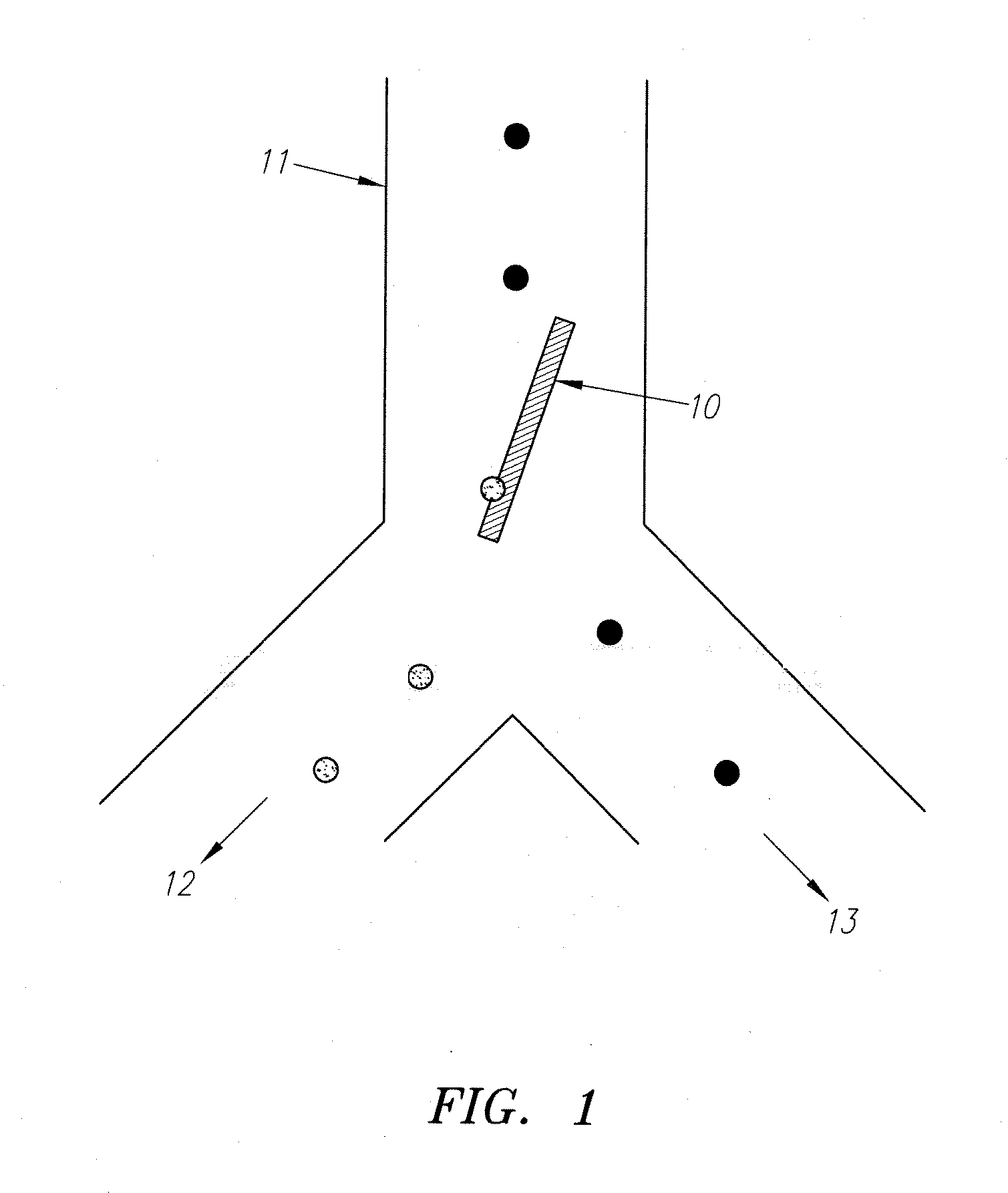
[0058]FIG. 1 shows one embodiment of an optical switch 10 that serves to sort cells in a 1×2 microfluidic channel network, i.e. a network with one main input channel 11 and two output channels 12 and 13 extending from a bifurcation junction. A “Y” geometry for the bifurcation junction is shown in FIG. 1, but other bifurcations such as a “T” geometry may also be used. In general these microfluidic channels are produced in optically transparent substrates to enable projection of the optical switch and other cell detection optics into the channel. This substrate is typically, but not limited to, glass, quartz, plastics, e.g., polymethylmethacrylate (PMMA), etc., and other castable or workable polymers (e.g. polydimethylsiloxane, PDMS or SU8). The depth of the microfluidic channels is typically in, but not limited to, the range 10 μm to 100 μm. The width of the microfluidic channels is typically, but not limited to, 1 to 5 times the depth. The cross section is typically rectangular, or ...


PUM

PropertyMeasurementUnit
diametersaaaaaaaaaa
diametersaaaaaaaaaa
diameteraaaaaaaaaa

Abstract

Apparatus and Methods are provided for a microfabricated fluorescence activated cell sorter based on a switch for rapid, active control of cell routing through a microfluidic channel network. This sorter enables low-stress, highly efficient sorting of populations of small numbers of cells (i.e., 1000-100,000 cells). The invention includes packaging of the microfluidic channel network in a self-contained plastic cartridge that enables microfluidic channel network to macro-scale instrument interconnect, in a sterile, disposable format. Optical and / or fluidic switching forces are used alone or in combination to effect switching.

Description

FIELD OF THE INVENTION [0001]This invention relates to methods and apparatus for the use of forces in a microfluidic channel network to provide a switch that enables selective routing of target cells through the network to sort them from non-target cells and collect them. Of particular interest are optical or fluidic switching forces.BACKGROUND OF THE INVENTION [0002]Conventional fluorescent activated cell sorters (FACS) are widely used in research and clinical applications1. These instruments are capable of very fast, multiparameter analysis and sorting but generally require large sample volumes, a trained operator for operation and maintenance, and are difficult to sterilize. FACS instruments are able to analyze as few as 10,000 and as many as tens of millions of cells. However, below 100,000 cells the ability to perform sorting diminishes1. Other separation methods such as magnetic beads don't require as many cells as FACS but they suffer from nonspecific binding, aggregation of ...

Claims


Application Information

Patent Timeline
Patent Type & Authority Applications(United States)
IPC IPC(8): C12M1/36C12M1/34F16K11/074
CPCB01L3/502761B01L3/502776B01L3/5088B01L2200/0652B01L2300/0864B01L2300/0874Y10T436/118339B01L2400/0487G01N15/1459G01N15/1484G01N2015/149G01N33/5005Y10T436/2575B01L2400/0454C12M47/04Y10T137/87161Y10T137/86509
Inventor BUTLER, WILLIAM FRANKZHANG, HAICHUANMARCHAND, PHILIPPEAHN, KEUNHOZHANG, YIFRANCIS, JOHNLAI, BENJAMINTU, EUGENE
Owner PROGENITY INC
Why Eureka
Try Eureka