Adjust Equipment and Method for Array Antenna Transmitting Link

a technology of array antenna and transmitting link, which is applied in the field of wireless communication technology, method and apparatus for calibrating the transmitting link of array antenna, to achieve the effects of fine convergence accuracy, fast speed of convergence and simple algorithm

Inactive Publication Date: 2008-10-23
ZTE CORP
View PDF22 Cites 27 Cited by
  • Summary
  • Abstract
  • Description
  • Claims
  • Application Information

AI Technical Summary

Benefits of technology

[0021]Comparing the apparatus and method of the present invention with prior array calibration art, it doesn't use the calibration transceiver apparatus and beacon antenna dedicated for the calibration of array antenna, but use the method of signal power detecting to calculate the gain calibration weight and transmission phase calibration weight, so the algorithm is simp

Problems solved by technology

In the cellular wireless communication system, with the increasing of the number of user, the jamming of the frequency spectrum and the distortion from the same channel become worse.
The more the cell of wireless communication network, the worse the same frequency distortion, thereby same frequency distortion will directly affect the receiving effect of base station and mobile terminals, inducing the reduce of base station's effective cover radius and degrading the quality of communication.
But, there are altitude and phase errors between the receiving channel and transmission link, the directional accuracy will be affected by the directly usage of uplink beam weight, so it is need to calibrate the uplink, downlink channel and feeder cable to compensate the altitude and phase errors.
(1) In U.S. Pat. No. 4,448,155 for “Method and apparatus for self-calibration and phasing of array antenna” and China Patent No. 01800020.7 for “Apparatus for array antenna wireless communication and method for calibration”, a kind of methods for calibrating the array antenna and transmission link is set forth, this method is to measure the gain and phase of each transmission link using instrument at the project field, then to calibrate the array using the measured result. The most disadvantage of this method is that it uses the off-line calibrating manner, and it can not calibrate the time-varied array error. It is not benefit to the engineering usage and maintenance, particularly, it is not suitable for the running communication system.
(2) In U.S. Pat. No. 6,615,024 for “Method and apparatus for determining signatures for calibrating a communication station having an antenna array”, China Patent No. 00815528.3 for “Method and apparatus for calibrating smart antenna array” and China Patent No. 02142694.5 for “Method and apparatus for calibrating antenna array”, a kind of methods to calibrate the array antenna is set forth. In these technical schemes, a beacon antenna and corresponding transceiver of calibrating signal need to be placed in the far field area and near field area of antenna array. During the calibration of uplink, the calibration signal is transmitted by beacon antenna and it is received by base station; during the calibration of downlink, the calibration signal is transmitted by base station and it is received by beacon signal, then the calibration weight is calculated o

Method used


Image

  • Adjust Equipment and Method for Array Antenna Transmitting Link
  • Adjust Equipment and Method for Array Antenna Transmitting Link
  • Adjust Equipment and Method for Array Antenna Transmitting Link

Examples


first embodiment

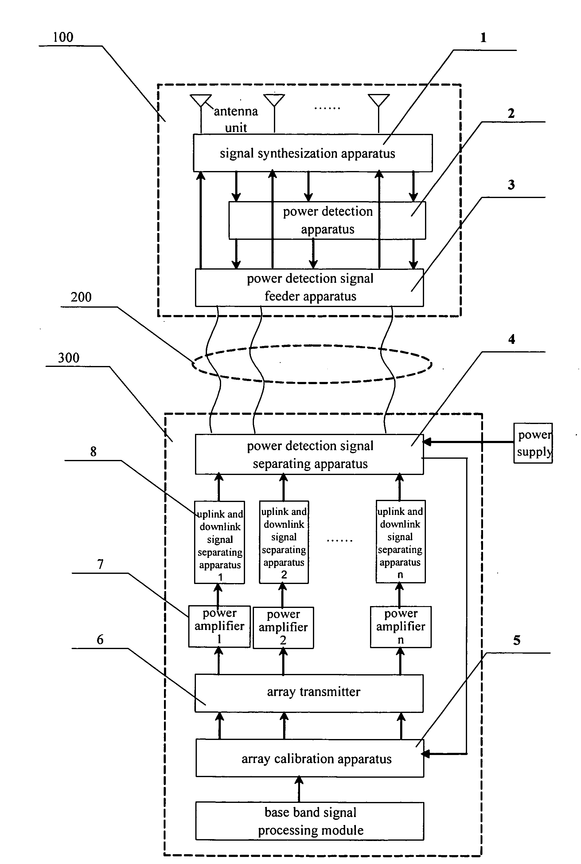
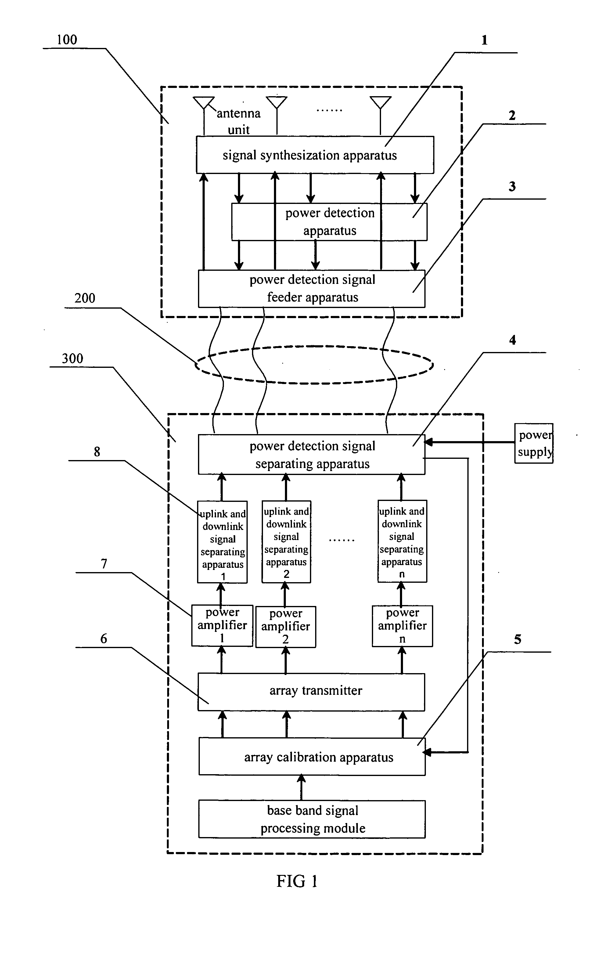
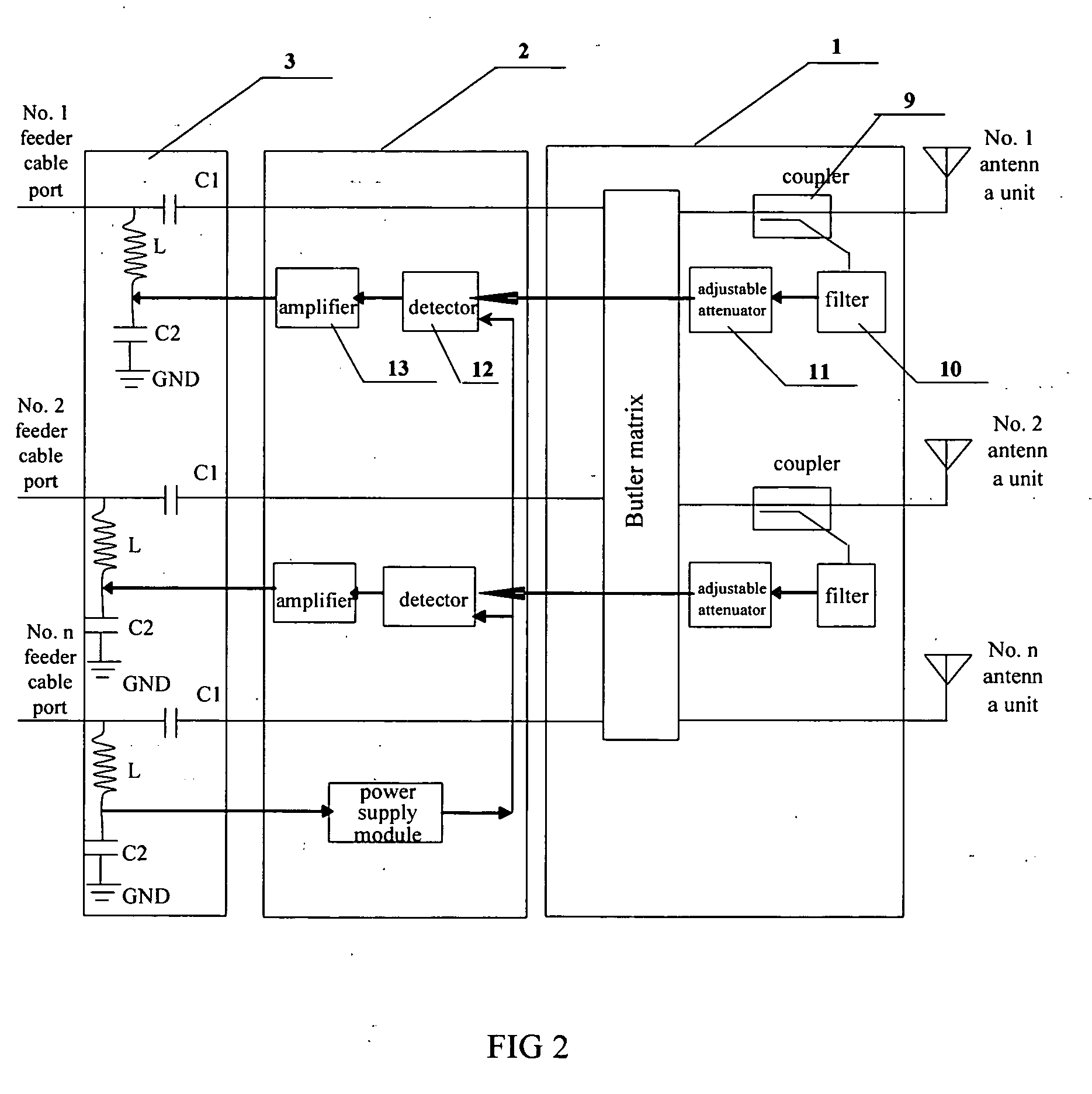
[0053]For the first embodiment using Bulter matrix to realize the downlink beam forming, firstly, control all of the transmission link to send signal with same phase in base band, then select the first transmission link as the reference channel, the other channel as the channel to be calibrated, adjust the phase of transmitting signal for the calibrating channel, make the signal power of first antenna unit is at maximum, and the signal powers of other antenna unit are at minimum, save the phase adjusting coefficient of transmission link at this time, which is represented by vector [0 Φadj1 . . . Φadjn], then calculate the inverse matrix WbutH, or Wbut−1 of the equivalent transmission coefficient matrix of Bulter matrix, and choose the first line vector of the above inverse matrix, which is respected by Vbulter,1=[Φ1,1 Φ1,2 . . . Φ1,n], then the initial value of phase calibration weight for transmission link is

[0φ1,1φadj2φ1,2…φadjnφ1,n].

second embodiment

[0054]For the second embodiment which is forming the downlink beam at base band, firstly, choose a transmission link as reference channel, the other transmission links as reference channels, control the reference channel and one of the channel to be calibrated to sending signal simultaneously, adjust the phase of base band signal in the channel to be calibrated, make the power of synthesized signal of the signals transmitted by the two channel at minimum, then the conjugate of the phase adjusting coefficient for the channel to be calibrated is the initial value of phase calibration weight for this channel; if the power of synthesized signal is at maximum, then the phase adjusting coefficient for the channel to be calibrated is the initial value of phase calibration weight for this channel. Choose another channel to be calibrated, repeat the depicted operation, until get the initial values of phase calibration weight for all of the transmission links.

[0055]After getting the initial v...


PUM


Abstract

Adjust equipment and method for array antenna transmitting link, include: power detect device, signal synthesize device and array adjust device; the downlink signal of the transmitting link processed by the power detect device and be transmitted to the power detect signal feed device, and then transmitted to the signal synthesize device; signal synthesize device depart the part of radio frequency signal, output to the power detect device for the power detect; output the power signal to the power detect signal feed device, add the power signal and high frequency signal, power detect signal depart device pick the power signal from the mixed signal, regulate the weight of the adjustment. This invention never use the special adjust signal transmitting device and becoming antenna, placed by using method of signal power detect to calculate the adjust weight value and transmitting phase adjust weight value of the transmit gain, the speed of the constringency become faster.

Description

FIELD OF THE INVENTION[0001]The present invention relates to the technology for calibrating the array antenna in the field of wireless communication technology, and more specifically, relates to a method and apparatus for calibrating the transmit link of array antenna.BACKGROUND OF THE INVENTION[0002]In the cellular wireless communication system, with the increasing of the number of user, the jamming of the frequency spectrum and the distortion from the same channel become worse. To solve such problems, it is desired to improve the quality of cellular wireless communication system, to increase the coverage area of base station, and to increase the capacity of system by using smart antenna technology and array signal processing technology.[0003]For a base station in the wireless communication network, there are signals coming from the mobile terminals in local cell as well as the signal with same frequency coming from the mobile terminals in other cell inside the received uplink sign...

Claims


Application Information

Patent Timeline
IPC IPC(8): H04B17/00H04B7/005
CPCH04B17/12H04W52/04H04B7/005H04B7/02H04B7/155
Inventor WANG, WENJIEGUO, TIANSHENG
Owner ZTE CORP
Why Eureka
Try Eureka