
Water treatment

a water treatment and water technology, applied in water/sludge/sewage treatment, specific water treatment objectives, lighting and heating apparatus, etc., can solve the problems of reducing the efficiency of water treatment. , to achieve the effect of reducing the overall utility, and reducing the cost of treatmen

Inactive Publication Date: 2008-10-30
HEBERT CLAUDE L
View PDF6 Cites 20 Cited by
  • Summary
  • Abstract
  • Description
  • Claims
  • Application Information

AI Technical Summary

Benefits of technology

[0010]It is an object of the present invention to provide a system suitable for chillers or other heat exchangers and which system can prevent scaling and where scaling has occurred, can remove the scale.

Problems solved by technology

Numerous heating and cooling systems using water circulation in closed loops age prematurely.
In many buildings and industrial plants, these CVC systems show signs of deterioration and weakening performance signs after only a few years.
This loss of efficiency is not always quickly detected right away, because it is not very apparent if one does not pay close and regular attention to it.
Eventually, this will translate in pumping difficulties and poor performance of the thermo-exchange equipments.
This loss in performance is usually caused by corrosion and scaling of the piping system.
If no preventive action against corrosion and limestone deposits is taken, they have to be dissolved in an acid solution, which is costly and damaging to the environment.
This must be repeated regularly since it does not prevent any ulterior limestone deposits in the circuits.
Furthermore, each acid treatment will cause corrosion of the metal installations, therefore reducing their durability.
Unfortunately, the limitation in water changing does not immediately eliminate all contaminants and a prolonged stay of the fluid inside the circuit is not always an advantage.
The water circulating through the closed loops usually contains fine particles in suspension which can cause many problems like scaling and abrasion.
This invariably results in abnormally quick wear of the components et loss of efficiency.
However, the most part of the particles in suspension contained the water of these networks are caused by corrosion.
The presence of oxygen, the different metals and microbiological activity are the main causes of this corrosion.
Oxygen, even in low concentration, always causes corrosion.
Without suitable preventive measures, this dissolved gas will be responsible for stringing degradation, the most frequent type of corrosion of water circulation systems.
Contact between different metals is not unusual in these loops and this can cause corrosion of galvanized pipes.
The presence of residue on the metallic surfaces is always a source of problems and it is always best to take preventive measures against this.
However, when residue has already started accumulating inside the piping network, any preventive effort will have little effect and deterioration will continue to progress.
It is in fact impossible to obtain a reasonable protection if the surfaces to be protected are not in the right condition for it.
On one hand, the corrosion inhibitors cannot be efficient on blocked surfaces and on the other hand, residue accumulation is a good place for microbic growth.
Letting a blocked piping system stay that way will only make things worse and will lead to corrosion and gradual deterioration of the surfaces.

Method used


Image

  • Water treatment
  • Water treatment
  • Water treatment

Examples


Embodiment Construction

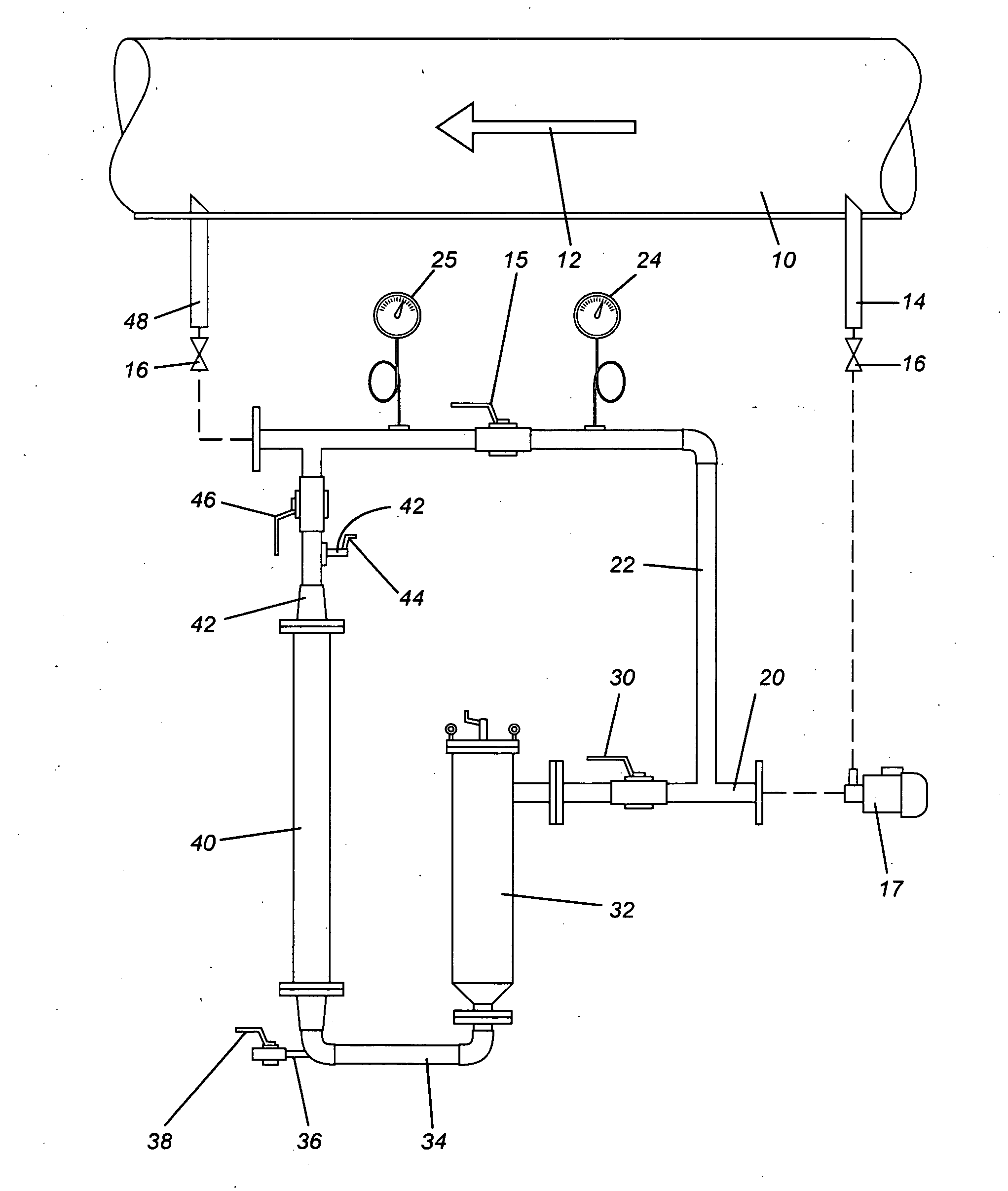
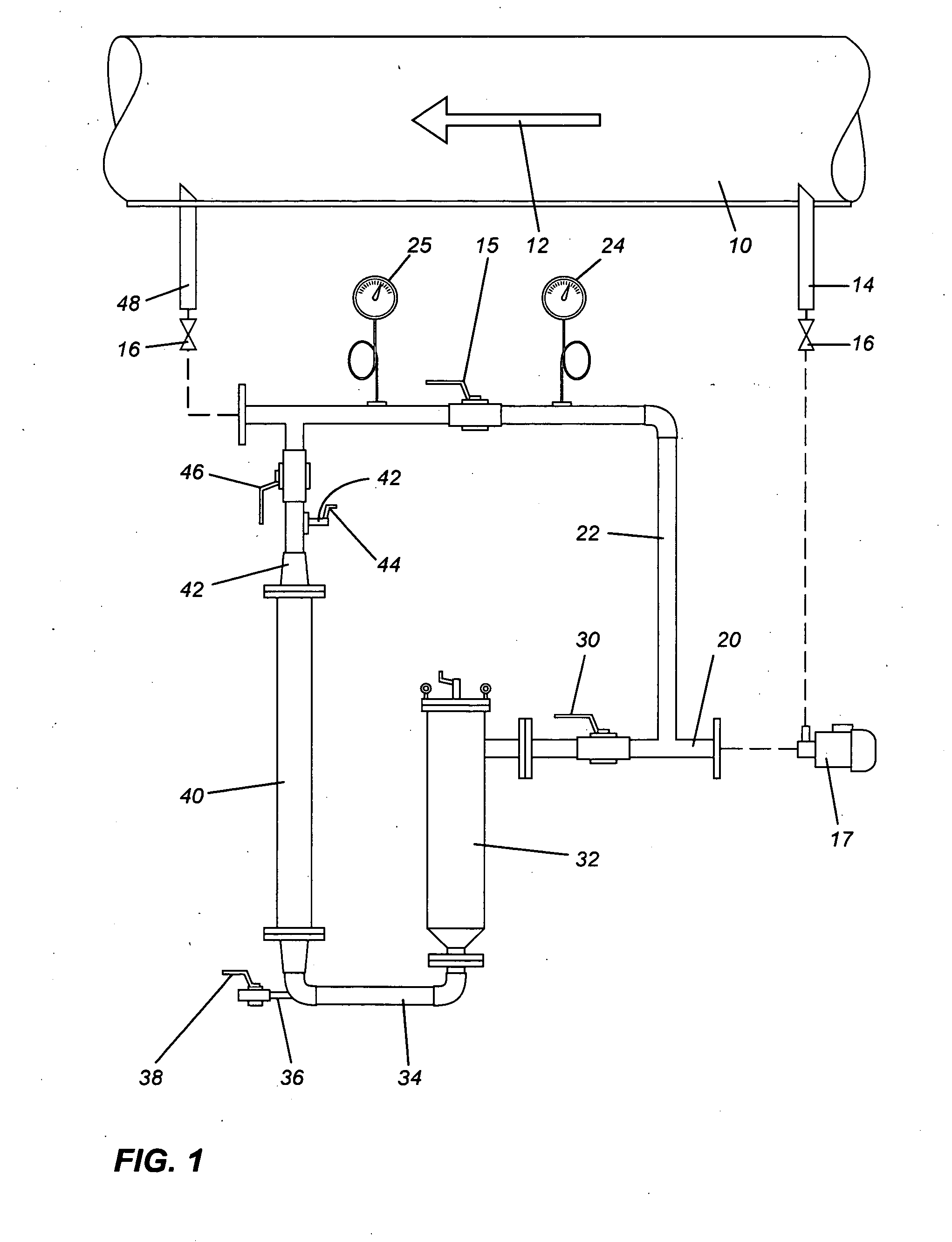
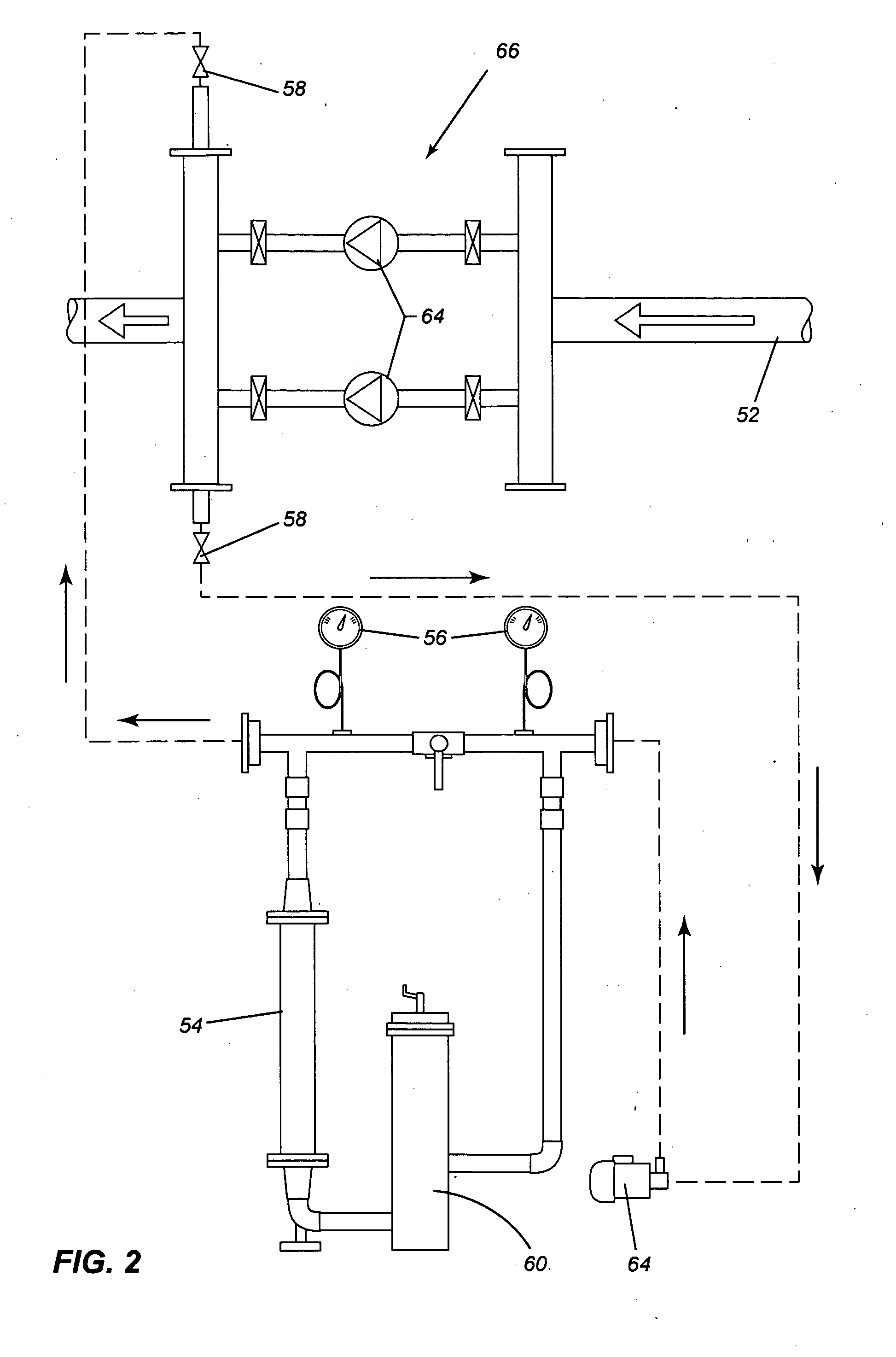
[0021]Referring to the drawing in greater detail and by reference characters thereto, there is illustrated a treatment system according to an embodiment of the present invention. The system is designed to be used with a closed circuit heat exchanger which includes a pipe 10 having fluid circulating in the direction indicated by arrow 12.

[0022]The system will include a conduit 14 which is tapped into pipe 10 such that a certain portion of the water within the heat transfer circulation will be diverted thereto. Preferably, the amount is between 5 and 15 percent and even more preferably between 8 and 10 percent of the total flow.

[0023]Conduit 14 includes a valve 16 thereon and is provided a pump 17 on the line, depending upon the desired pressures.

[0024]A system inlet 20 has a bypass conduit 22 located thereat. On bypass conduit 22 there are provided pressure gages 24 and 25 with a valve 26 therebetween.

[0025]Treatment line 28 has a valve 30 thereon. A filter 32 having the desired filt...


PUM

PropertyMeasurementUnit
magnetic fieldaaaaaaaaaa
heataaaaaaaaaa
pressure dropaaaaaaaaaa

Abstract

A method and device for removing scaling from the interior of a conduit used in a heat transfer device, the method comprising the steps of diverting a portion of the fluid from the conduit, passing the diverted portion through a filter, passing the filtered portion through a magnetic field, and reintroducing the fluid into the conduit. The method of the present invention can also be used with chillers to control bacterial growth therein.

Description

FIELD OF THE INVENTION[0001]The present invention relates to a method for treating water and a system for treating water, particularly industrial water used in heat exchangers and chillers.BACKGROUND OF THE INVENTION[0002]Numerous heating and cooling systems using water circulation in closed loops age prematurely. In many buildings and industrial plants, these CVC systems show signs of deterioration and weakening performance signs after only a few years. This loss of efficiency is not always quickly detected right away, because it is not very apparent if one does not pay close and regular attention to it. Eventually, this will translate in pumping difficulties and poor performance of the thermo-exchange equipments. This loss in performance is usually caused by corrosion and scaling of the piping system.[0003]If no preventive action against corrosion and limestone deposits is taken, they have to be dissolved in an acid solution, which is costly and damaging to the environment. This m...

Claims


Application Information

Patent Timeline
Patent Type & Authority Applications(United States)
IPC IPC(8): F28G13/00C02F1/48
CPCC02F1/004C02F1/48C02F2103/023C02F2301/043C02F2303/22F28G13/00
Inventor HEBERT, CLAUDE L.
Owner HEBERT CLAUDE L
Learn More