Inverter apparatus and a semiconductor device used for the same

a technology of inverter apparatus and semiconductor device, which is applied in the direction of dynamo-electric converter control, dynamo-electric gear control, electric generator control, etc., can solve the problems of high cost, high speed of three-shunt detection method, and many problems of single-shunt detection method, so as to improve torque and speed ripple, and stabilize control

Active Publication Date: 2008-10-30
RENESAS ELECTRONICS CORP
View PDF1 Cites 32 Cited by
  • Summary
  • Abstract
  • Description
  • Claims
  • Application Information

AI Technical Summary

Benefits of technology

[0021]Accordingly, even if the current detectors have intrinsic unevenness, the present invention can solve the unevenness. As a result, it is possible to obtain an inverter apparatus and the like which are capable of achieving lower costs, improving torque and speed ripples, and stabilizing the control.

Problems solved by technology

However, due to its nature, the single-shunt detection method faces many practical problems in order to achieve efficient control with a simple configuration.
One of the problems is that the method requires high performance and high speed for microprocessor for controlling the inverter and the like.
However, the three-shunt detection method requires current detection at high accuracy.
An accurate current value cannot be obtained with an offset caused in an operational amplifier even if a shunt resistor detects an accurate potential difference in each phase.
Nevertheless, this attempt contradicts market demands such as cost reduction.
As described previously, providing a current detector with high accuracy is not a favorable problem-solution approach, and it is preferable to provide a motor system and an inverter which can fulfill their functions, albeit at poor detection accuracy, as described in Patent Document 4.
In short, since the phases are measured separately, the measured values differ from each other depending on the time of each measurement, thereby causing deviations in the values.
These deviations may degrade a performance of a motor control device.
These ripples could degrade performance of a control system.
If the current detector causes deviation in the detection performance or other unevenness due to existence of detection deviation or the like, detection error attributable to the current detector occurs.
As a consequence, the detected currents are judged not to be balanced, i.e. imbalanced even when the currents are actually balanced.
As a consequence, the control system becomes unstable by contraries.

Method used


Image

  • Inverter apparatus and a semiconductor device used for the same
  • Inverter apparatus and a semiconductor device used for the same
  • Inverter apparatus and a semiconductor device used for the same

Examples


first embodiment

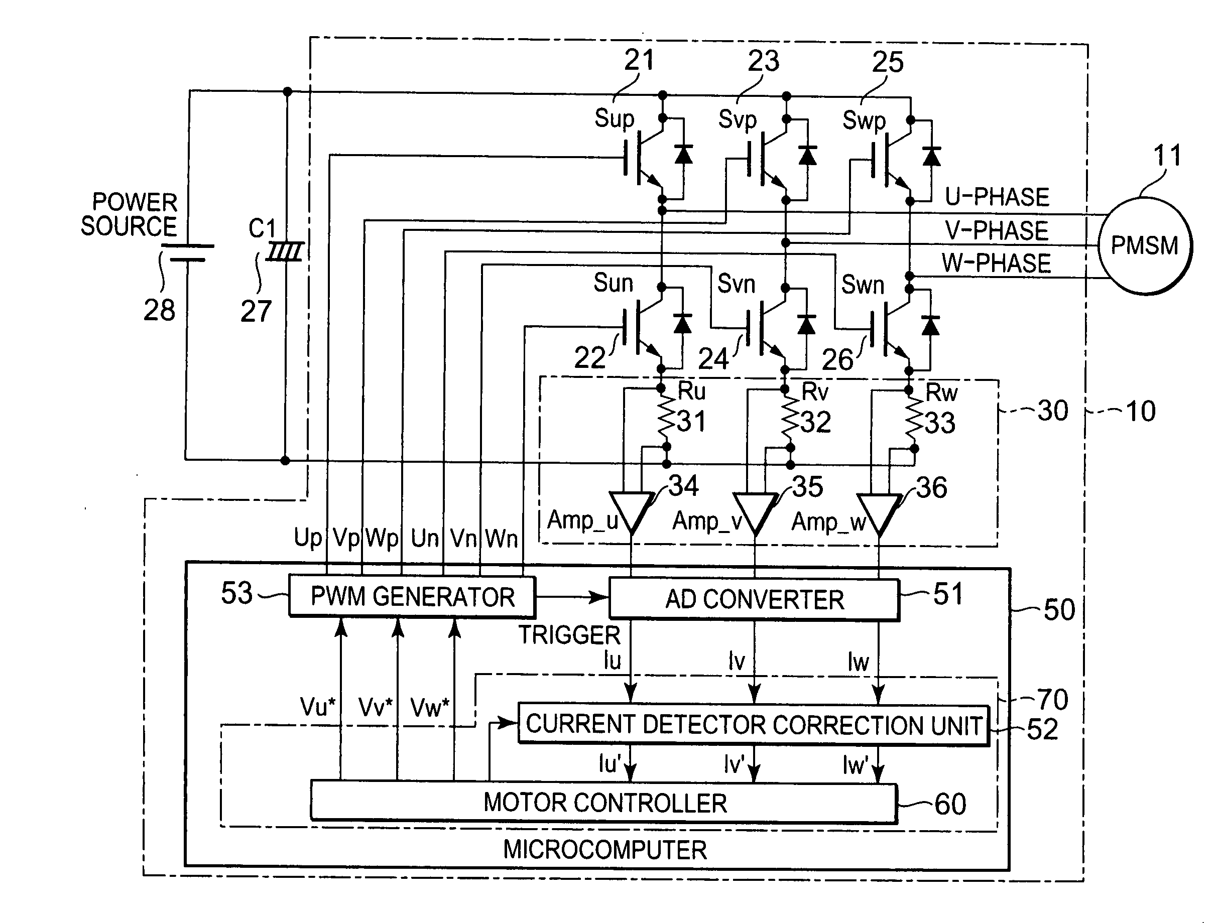
[0044]FIG. 6 shows an inverter apparatus 10 according to a first embodiment of the present invention. Although this drawing seems similar to FIG. 1 described in the Related Art, a key difference therebetween is that this configuration includes a current detector correction unit 52 for performing correction of an imbalance among the current detectors explained in the principle diagrams. In the drawing, reference numeral 50 denotes a microcomputer, which is configured to control the switching elements, i.e. to perform motor control, and is usually formed of a semiconductor device. Moreover, although it is not shown in the illustration of the inverter apparatus in FIG. 6, this configuration also has other features such as a method of controlling the switching elements in order to perform correction of the deviation among the current detectors, for example. In this way, the first embodiment can also be grasped as the invention of a motor controlling method using the inverter apparatus 1...

second embodiment

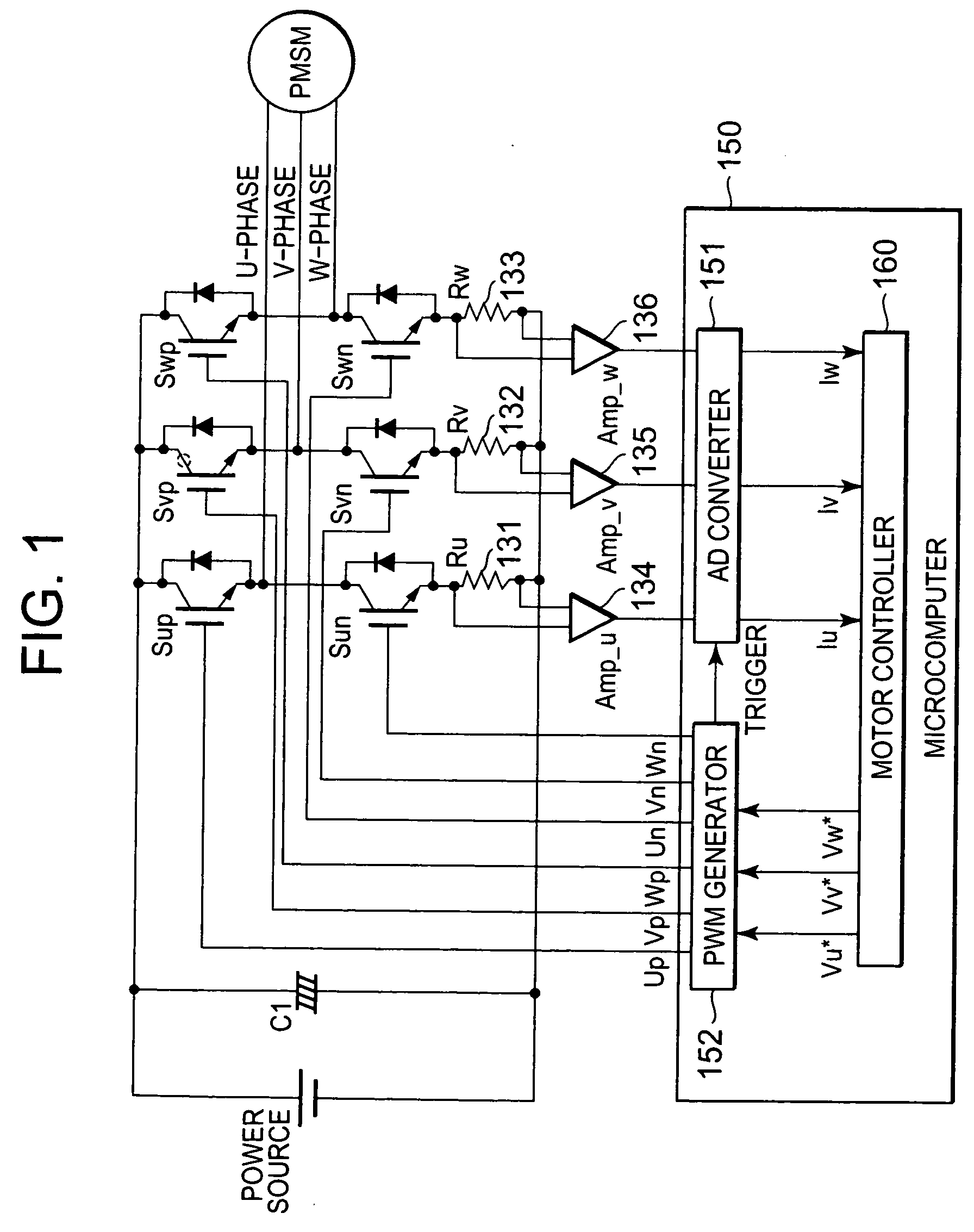
[0080]The present invention has been described above in detail by using the three-shunt detection method as the example. Now, the two-shunt detection method will be briefly described with reference to FIG. 15. An inverter apparatus 80 shown in FIG. 15 includes current detectors 38 provided with only two amplifiers. That is, a major difference from FIG. 6 of the first embodiment is lack of the amplifier in the V-phase. Although a resistance element 42 is provided in the current detectors 38, this is another difference from the first embodiment because this is not the shunt resistance element as the current detector but is the resistance element intended to maintain the balance among the phases by simply equalizing a voltage drop relative to the U-phase and the W-phase as much as possible. Here, it is also possible to omit the resistance element 42. Other features are similar to the first embodiment, and further description on FIG. 15 will therefore be omitted. Moreover, in the two-sh...

third embodiment

[0087]The first embodiment and the second embodiment have described the example of using the PWM method in order to obtain the measurement circuit shown in FIG. 4B. However, it is not always necessary to use the PWM method. It is also possible to apply a method using a single pulse as described below.

[0088]FIG. 16 shows the method using the single pulse. In short, means for controlling the switching elements Sup 21 and Sun 22 is different from the first embodiment. Other features are the similar to the first embodiment. Accordingly, only the different features will be described below in detail for avoidance of overlapping explanation. Specifically, the method corresponding to FIG. 4A is shown in FIG. 11 while the method corresponding to FIG. 4B is shown in FIG. 13. Moreover, FIG. 12 showing the control of the switching elements Sup 21 and Sun 22 is replaced by FIG. 15.

[0089]This control method will now be described in detail. First, the switching element Sup 21 is turned on for a pr...


PUM


Abstract

FIGS. 4A and 4B are principle diagrams for correcting deviations among current detectors of a three-phase motor 19 in an inverter apparatus of the present invention, which includes bidirectional switching elements 13 to 18. FIG. 4C shows on and off states of switches in the cases of FIGS. 4A and 4B, in which 1 and 0 mean on- and off-states, respectively. The states shown in FIGS. 4A and 4B are alternately repeated by controlling the switches, and measurement for correcting the deviations among the current detectors are obtained in the state shown in FIG. 4B. Specifically, in FIG. 4B, currents having the same amplitude flow on a U phase and a V phase. Accordingly, a difference in the measured data represents a difference in performances of the current detectors. In the state of normal use, the inverter apparatus is operated by correcting detected current values based on the measurement data.

Description

BACKGROUND OF THE INVENTION[0001]1. Field of the Invention[0002]The present invention relates to an inverter apparatus configured to execute instantaneous current control and thereby to drive motors including three-phase alternating-current motors (such as an induction motor or a permanent magnet synchronous motor) and to a semiconductor device and the like used for the same.[0003]2. Description of the Related Art[0004]Today, inverter apparatuses configured to execute instantaneous current control are widely used in refrigerating and air-conditioning machines, air blowers, washing machines, compressor drivers, and the like. Vector control is widely applied to control of, particularly, alternating-current motors such as induction motors or permanent magnet synchronous motors. Put simply, the vector control is a control method by means of detecting a motor current and performing special calculation to separate the motor current into a magnetic flux component and a torque component. Wh...

Claims


Application Information

Patent Timeline
Patent Type & Authority Applications(United States)
IPC IPC(8): H02P27/06H02P1/26H02M7/48H02P21/00H02P21/22H02P21/34H02P27/04H02P27/08
CPCH02P21/0042H02P21/146H02P21/18H02P21/26
Inventor HAYASHI, YOICHIFUKUMOTO, TETSUYA
Owner RENESAS ELECTRONICS CORP
Why Eureka
Try Eureka