Ultrasound Calibration and Real-Time Quality Assurance Based on Closed Form Formulation

Active Publication Date: 2008-10-30
THE JOHN HOPKINS UNIV SCHOOL OF MEDICINE
View PDF9 Cites 60 Cited by
  • Summary
  • Abstract
  • Description
  • Claims
  • Application Information

AI Technical Summary

Benefits of technology

[0018]An advantage of the present invention is to provide more reliable real-time ultrasound-based 3D imagery for use during medical procedures in that the ultrasound probe may be spatially calibrated intra-operatively. This helps mitigate post-calibration changes that may degrade the accuracy of 3D imagery without warning.
[0019]Another advantage of the present invention is to provide a more efficient and robust spatial calibration of an ultrasound probe. By spatially calibrating the ultrasound probe based on the relative differences between two or more images of the same phantom, the resulting calibration is less dependent on the precision to which the spatial characteristics of the phantom are known.
[0020]Another advantage of the present invention is to simplify the ultrasound probe calibration process. The present invention identifies pixels corresponding to prominent feature points on a phantom, as opposed to segmenting an image in order to reconstruct an image of the phantom, which is more computationally intensive.
[0021]Additional features and advantages of the invention will be set forth in the description which follows, and in part will be apparent from the description, or may be learned by practice of the invention. The objectives and other advantages of the invention will be realized and attained by the structure particularly pointed out in the written description and claims hereof as well as the appended drawings.
[0022]To achieve these and other advantages and in accordance with the purpose of the present invention, a method for spatially calibrating an ultrasound probe comprises placing the ultr

Problems solved by technology

Image processing techniques such as segmentation are computationally intensive and may not be feasible to compute in real time, based on the number of images acquired.
The large number of images not only requires time to process, but it increases the likelihood of errors that may render the probe calibration matrix invalid.
Accordingly, a primary challenge in spatial calibration is in determining the probe calibration matrix RTP.
There are errors intrinsic to the conventional spatial calibration process that limit its precision and accuracy, including the following: imprecision in fabrication of the phantom, subsequent mechanical distortions of the phantom, lack of precision in characterizing the features of the phantom, spatial co-registration or ambiguities, and limits to numerical solution optimizations.
As such, the quality of

Method used


Image

  • Ultrasound Calibration and Real-Time Quality Assurance Based on Closed Form Formulation
  • Ultrasound Calibration and Real-Time Quality Assurance Based on Closed Form Formulation
  • Ultrasound Calibration and Real-Time Quality Assurance Based on Closed Form Formulation

Examples


Example

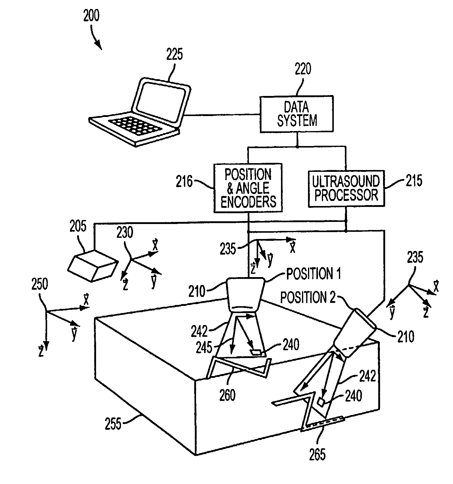
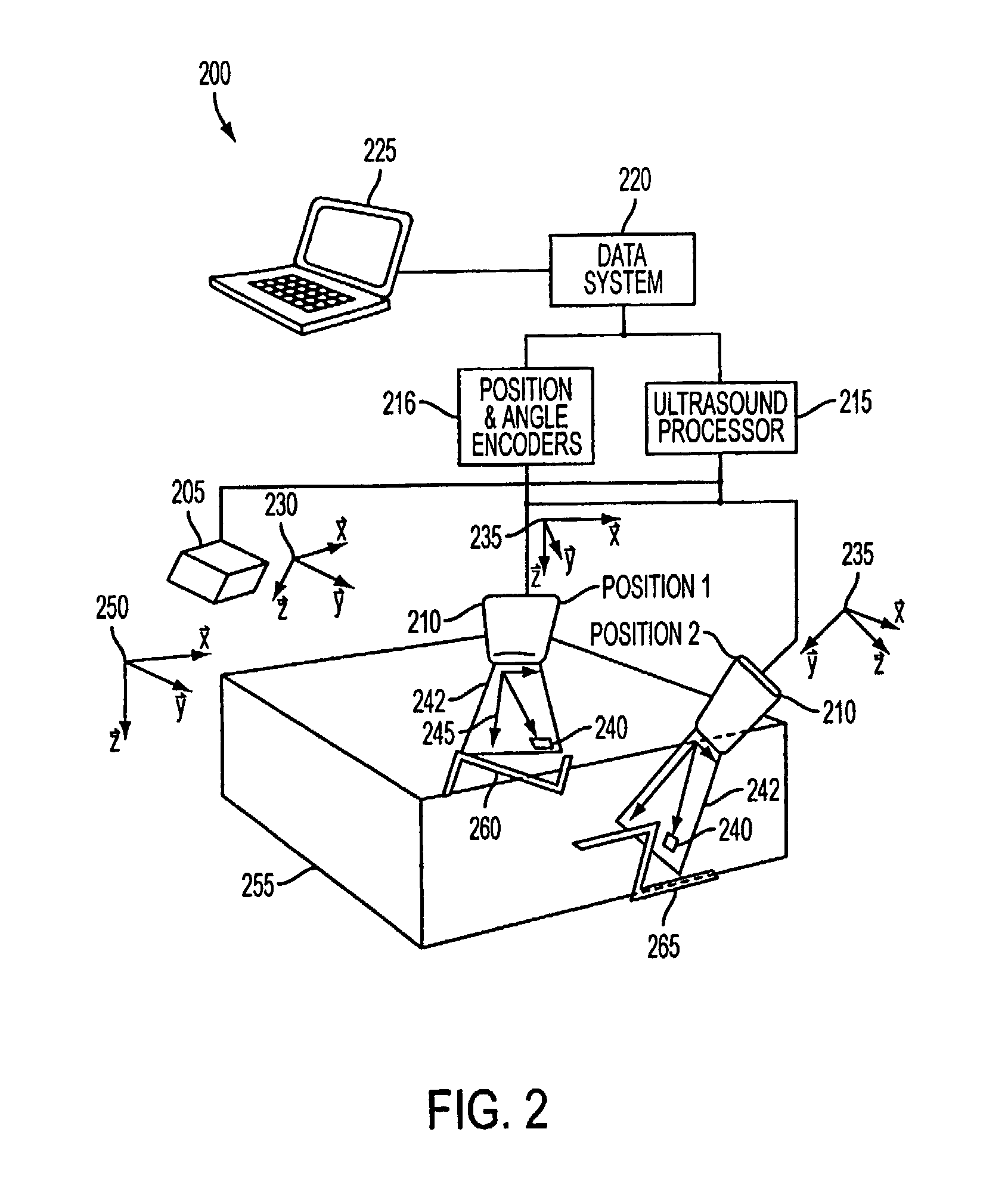
[0036]FIG. 2 illustrates an exemplary ultrasound imaging system 200 according to the present invention. The imaging system 200 includes an ultrasound transmitter 205 having a transmitter reference frame 230; an ultrasound probe 210 having a probe reference frame 235; position and angle encoders 216 for measuring the position and orientation of the probe reference frame 235 relative to the transmitter reference frame 230; an ultrasound processor 215 for providing power and signals to, and receiving signals from, the ultrasound transmitter 205 and the ultrasound probe 210; a data system 220 for sending commands to and receiving data from the ultrasound processor 215 and the position and angle encoders 216; and a user interface 225 connected to the data system 220. The ultrasound probe 210 may transmit and receive energy in a scan plane 242, which includes a plurality of pixels 240 within the scan plane 242 and having a pixel reference frame 245.

[0037]The exemplary system 200 acquires ...


PUM


Abstract

Disclosed is a system and method for intra-operatively spatially calibrating an ultrasound probe. The method includes determining the relative changes in ultrasound images of a phantom, or high-contrast feature points within a target volume, for three different ultrasound positions. Spatially calibrating the ultrasound probe includes measuring the change in position and orientation of the probe and computing a calibration matrix based on the measured changes in probe position and orientation and the estimated changes in position and orientation of the phantom.

Description

[0001]This application claims the benefit of U.S. Provisional Patent Application No. 60 / 562,460, filed on Apr. 15, 2004, which is hereby incorporated by reference for all purposes as if fully set forth herein.[0002]The research and development effort associated with the subject matter of this patent application was supported by the National Science Foundation under grant no. ERC 9731478.BACKGROUND OF THE INVENTION[0003]1. Field of the Invention[0004]The present invention involves the field of ultrasound imagery. More particularly, the present invention involves spatial calibration of ultrasound probes for intra-operative use.[0005]2. Discussion of the Related Art[0006]Computer Integrated Surgery has revolutionized surgical procedures, whereby 3D imagery of a target volume is created to enable a surgeon to more precisely and accurately position surgical tools within a patient. To serve this purpose, the imaging system, or guidance modality, should provide 3D imagery in real time; it ...

Claims


Application Information

Patent Timeline
IPC IPC(8): A61B8/00G01S7/52
CPCA61B8/00A61B8/587G01S7/5205A61B8/483A61B8/4245
Inventor BOCTOR, EMAD M.HAGER, GREGORY D.FICHTINGER, GABORVISWANATHAN, ANAND
Owner THE JOHN HOPKINS UNIV SCHOOL OF MEDICINE
Why Eureka
Try Eureka