
Machining center

a machining center and high-automatic technology, applied in the direction of charging manipulation, furniture, lighting and heating apparatus, etc., can solve the problems of reducing human labor requirements, imbalance in labor costs, and labor costs remaining a very high component of the cost of producing finished goods, so as to eliminate human operator requirements

Inactive Publication Date: 2008-11-06
ANN ARBOR MACHINE
View PDF3 Cites 16 Cited by
  • Summary
  • Abstract
  • Description
  • Claims
  • Application Information

AI Technical Summary

Benefits of technology

[0005]The machining center in accordance with this invention is capable of providing an extraordinary degree of automation and is capable of virtual elimination of human operator requirement. An idealized fully automated machining system in accordance with this invention could be operated in a “lights out” manner since human intervention and control is practically eliminated.

Problems solved by technology

In today's economic climate, particularly for Western countries, labor costs remain a very high component of the cost of producing finished goods.
This imbalance in labor cost greatly favors developing nations in the manufacture of finished goods for use throughout the world.
To date, however, machine operations have not reduced human labor requirements to the extent possible, and thus the cost imbalance mentioned previously continues to be a factor.
Moreover, highly automated machining systems presently available tend to be complex, costly and unreliable.

Method used


Image

  • Machining center
  • Machining center
  • Machining center

Examples


Embodiment Construction

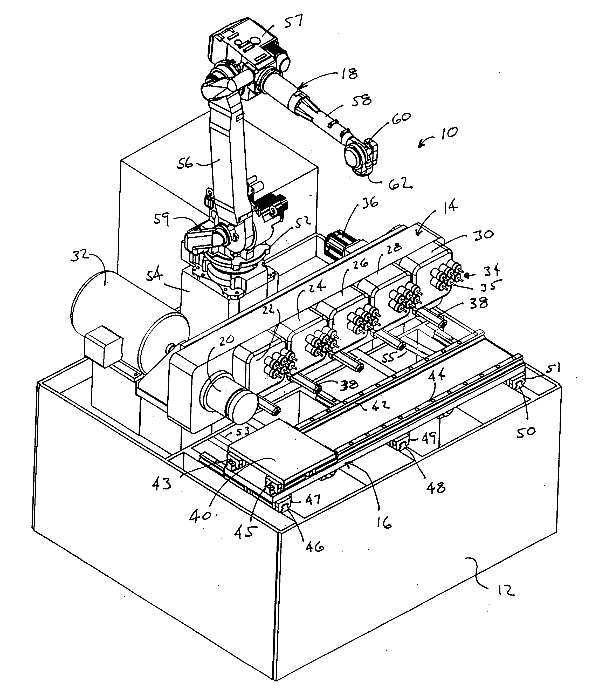
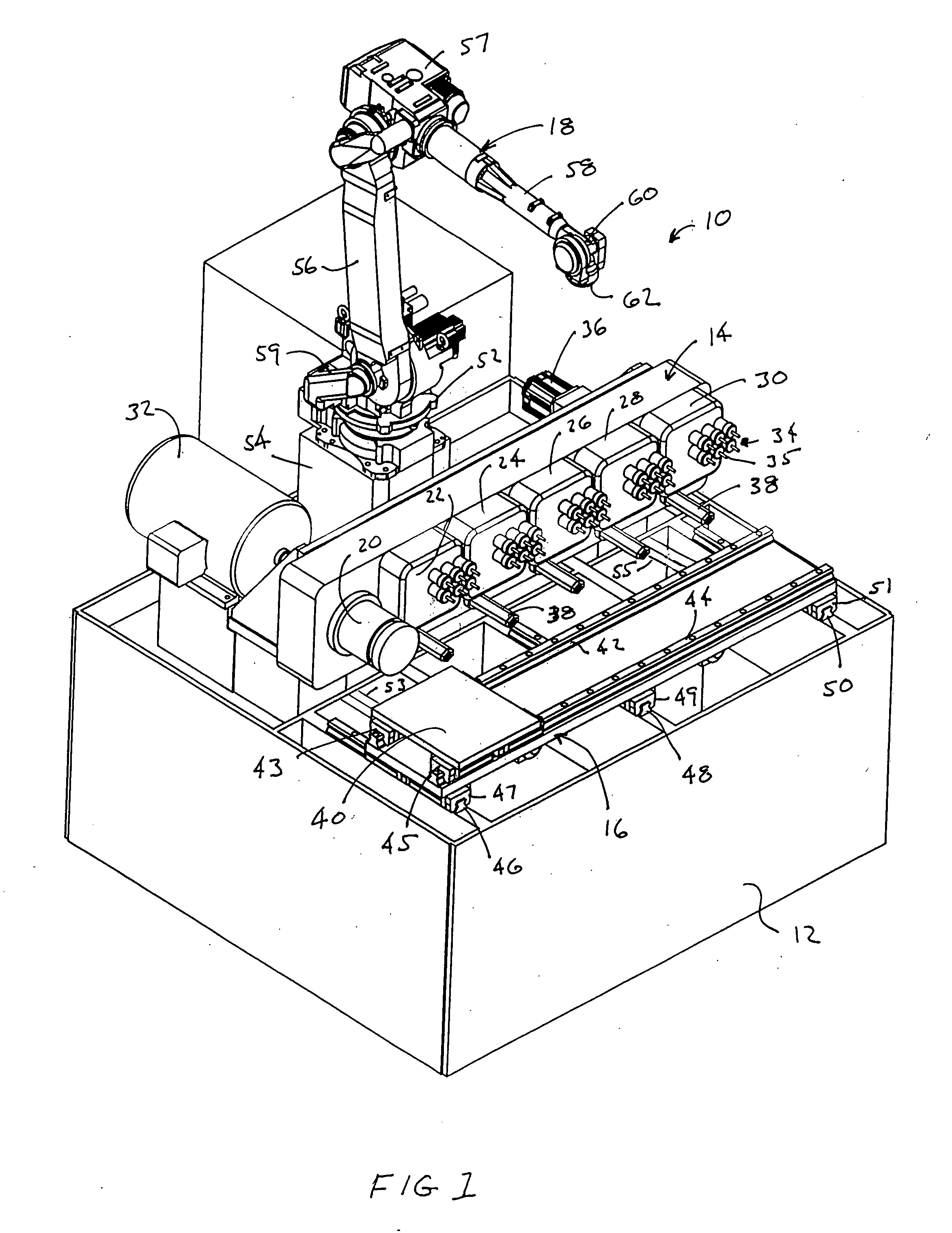
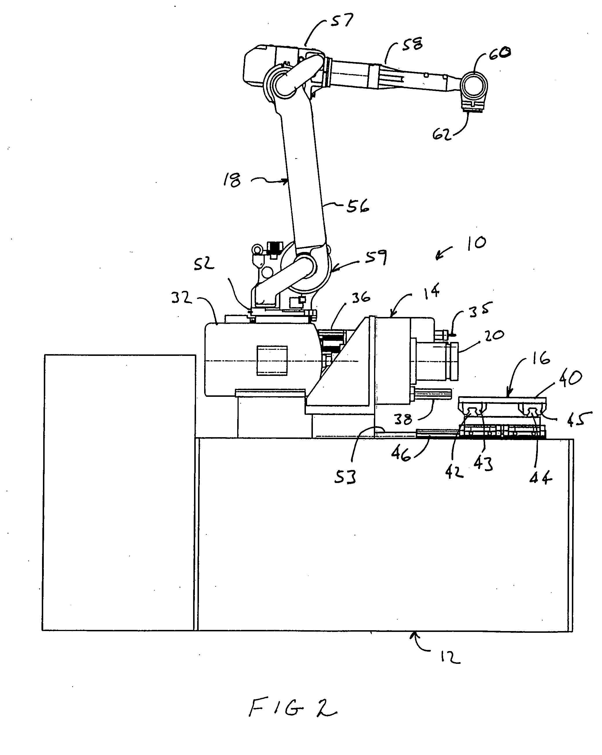
[0010]A machining center in accordance with the present invention is illustrated in FIGS. 1 through 3 and is generally designated by referenced number 10. Machining center 10 generally comprises machine base 12, master machining head 14, workpiece transport system 16, and robot actuator 18.

[0011]Machine base 12 provides a structural support for the remaining components of machining center 10 and is designed to be mounted to a factory floor. Machine base 12 would typically incorporate a subsystem for collecting machining fluids used in the machining operations of workpieces which can be oil or water based emulsion-type cutting fluids. A cutting fluid handling system (not shown) is provided for the collection, filtration, and transport of the machining fluids. Machine base 12 can be configured for standardized positioning on the workpiece floor for integration with other factory processing and automation systems.

[0012]Master machining head 14 illustrated in the figures provides a numb...


PUM


Abstract

A machining center is provided enabling a high degree of machining automation. The machining center includes a master machining head including multiple spindles mounted fixedly to the machining base. A workpiece transport system transports workpieces between machining stations and also moves it toward and away from the machining stations which are preferable fixedly mounted. Registration pins mounted to the master machine head register with a receiving socket carried by the workpiece platform or associated workpiece fixture. A robot actuator is provided which loads and unloads workpieces with the machining center 10 and can also potentially provide other functions such as tool inspection tool changing, workpiece repositioning.

Description

FIELD OF THE INVENTION[0001]This invention relates to a highly automated machining center for factory automation particularly adapted for forming metal parts.BACKGROUND OF THE INVENTION[0002]Industrial engineers have long sought to design machining operations for factories which provide low cost, high throughput, machining accuracy with high levels of quality control. In today's economic climate, particularly for Western countries, labor costs remain a very high component of the cost of producing finished goods. The hourly labor costs in some countries can be as low as one-tenth of that in Western countries. This imbalance in labor cost greatly favors developing nations in the manufacture of finished goods for use throughout the world. To address these economic factors, industrial engineers have developed many advanced manufacturing systems which use factory automation, including sophisticated robots which handle parts and position them for machining as well as inspection, packaging...

Claims


Application Information

Patent Timeline
IPC IPC(8): B23P21/00
CPCB23Q39/024B23Q2039/006Y10T408/385Y10T29/5124Y10T408/3806Y10T409/305264Y10T408/3833Y10T409/30532
Inventor BETZIG, ROBERTSINGLETON, BRIAN
Owner ANN ARBOR MACHINE
Learn More