Laser desorption - electrospray ion (ESI) source for mass spectrometers

a mass spectrometer and electrospray ion technology, applied in the direction of instruments, particle separator tube details, separation processes, etc., can solve the problems of reducing the analytical accuracy of large biomolecules

a mass spectrometer and electrospray ion technology, applied in the direction of instruments, particle separator tube details, separation processes, etc., can solve the problems of reducing the analytical accuracy of large biomolecules

US20080272294A1Inactive Publication Date: 2008-11-06THERMO FINNIGAN

Image

  • Laser desorption - electrospray ion (ESI) source for mass spectrometers
  • Laser desorption - electrospray ion (ESI) source for mass spectrometers
  • Laser desorption - electrospray ion (ESI) source for mass spectrometers

Examples


Embodiment Construction

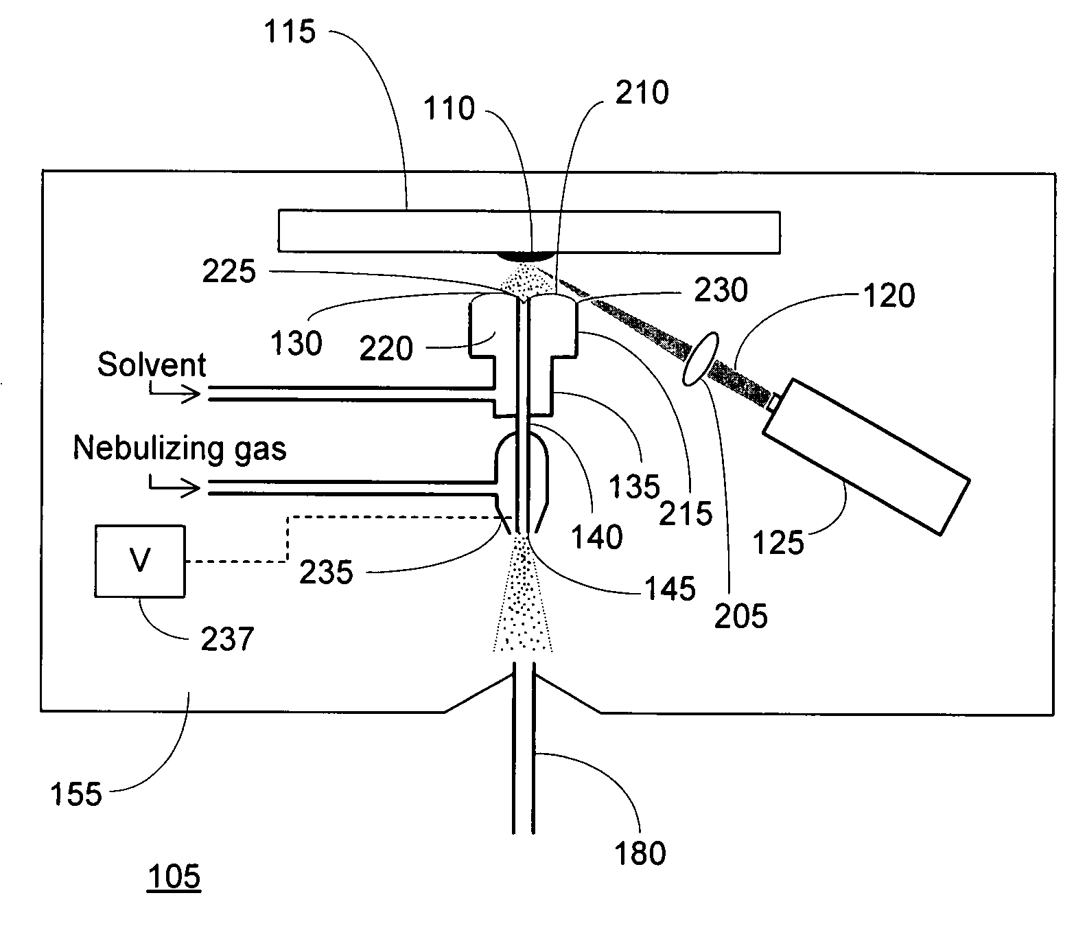
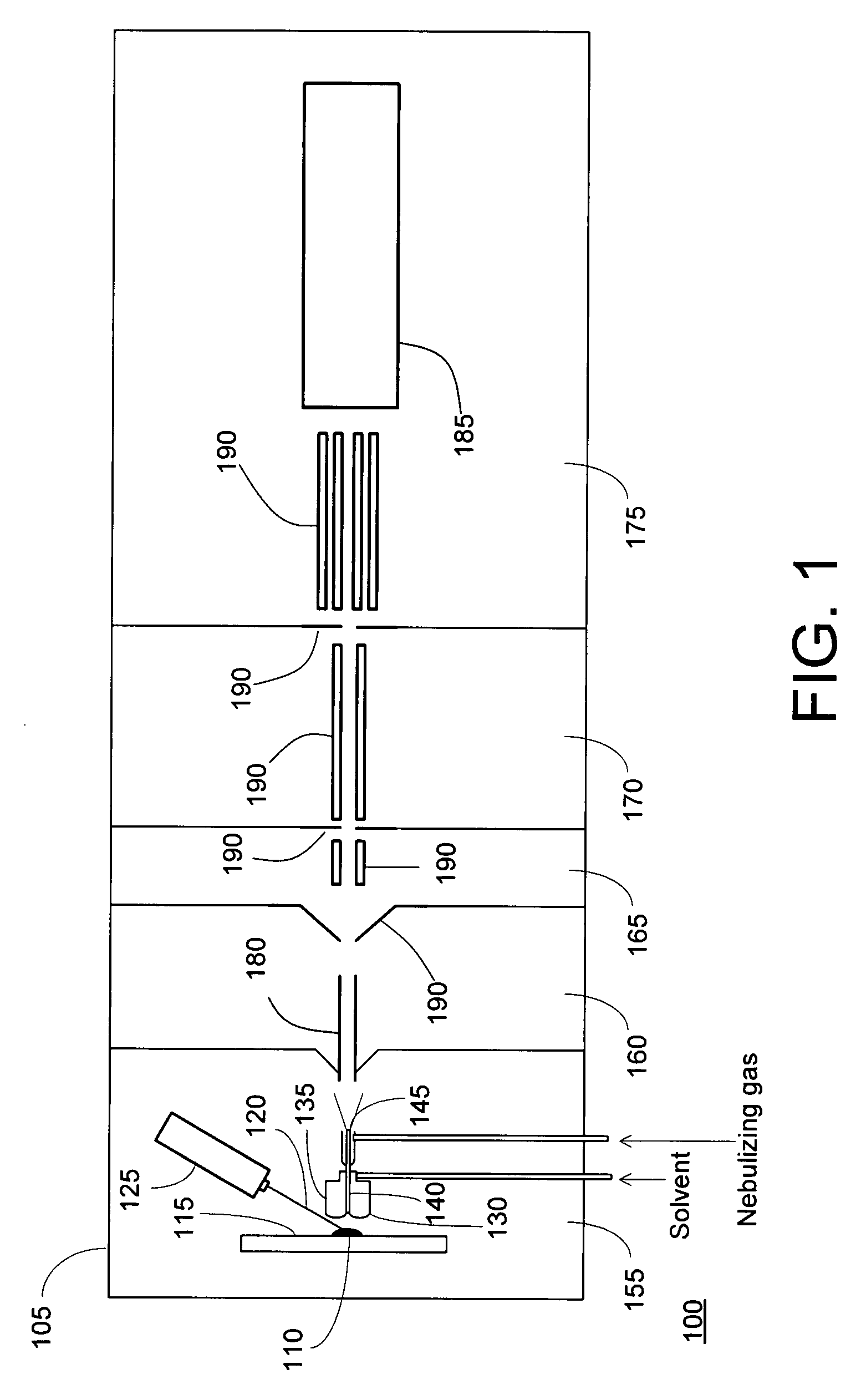
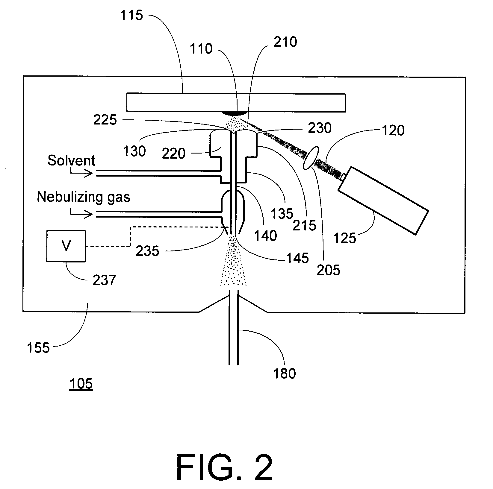
[0013]FIG. 1 is an overall schematic depiction of a mass spectrometer 100 utilizing a laser desorption-electrospray ion (LD-ESI) source 105 in accordance with an illustrative embodiment of the invention. A condensed-phase (solid or liquid) sample 110 is disposed on a sample support 115 and aligned with a radiation beam 120 emitted by a radiation source, such as laser 125. Irradiation of the sample causes analyte molecules to be desorbed from the surface. At least a portion of the desorbed analyte molecules contact a free surface of a solvent volume 130 held in close proximity to sample 110 by retaining structure 135 and are absorbed into solution. The solution containing the analyte molecules is drawn through an outlet passageway defined by central tube 140 and is conveyed therethrough to spray orifice 145. The central tube 140 (or the distal portion thereof) is maintained at an appropriate potential relative to other elements within ionization chamber 155 (the interior of which wil...


PUM


Abstract

An ion source is disclosed for forming multiply-charged analyte ions from a solid sample. A beam of pulsed radiation is directed onto a portion of the sample to desorb analyte molecules. A retaining structure holding a solvent volume is positioned proximate the sample. Desorbed analyte molecules contact a free surface of the solvent and pass into solution. The solution is then conveyed through an outlet passageway to an electrospray apparatus, which introduces a spray of charged solvent droplets into an ionization chamber.

Description

TECHNICAL FIELD[0001]The present invention is related to ion sources for mass spectrometers, and more particularly to a laser desorption source capable of producing multiply charged analyte ions from a sample.BACKGROUND[0002]Mass spectrometers are widely used instruments for providing information about the nature and structure of molecules, including large biomolecules such as peptides or proteins. An important component in the construction of a mass spectrometer system is a source for producing ions of the molecule or molecules of interest (i.e., the analyte molecules) to enable subsequent separation and detection by mass spectrometry.[0003]Matrix assisted laser desorption and ionization (MALDI) is one well-known technique for the production of analyte ions. The MALDI process may be conceptualized as having two steps. In a first step, the analyte is mixed with a solvent containing small organic molecules in solution, called a matrix. The matrix is chosen to have a strong absorption...

Claims


Application Information

Patent Timeline
06 Nov 2008
Publication
US20080272294A1
IPC
H01J49/10
CPC
H01J49/0463; H01J49/165
Inventors
KOVTOUN, VIATCHESLAV V.