Annular seal assembly for insertion between two relatively rotatable members, in particular a tub and a rotating shaft of the drum of a washing machine

a technology of annular seals and components, which is applied in the direction of engine seals, other washing machines, textiles and paper, etc., can solve the problems of high energy consumption of appliances, rapid wear of sealing lips, and relatively bulky seal assemblies and protective shields, and achieve the effect of improving performan

Active Publication Date: 2008-11-06
AB SKF
View PDF2 Cites 15 Cited by
  • Summary
  • Abstract
  • Description
  • Claims
  • Application Information

AI Technical Summary

Benefits of technology

[0014]In other words, the invention combines, in innovative manner, the technology described in EPO940610B1 for one of the two radial-sealing lips, and the technology described in EPO980999B1, the pertinent parts of which are also included herein purely by way of reference. According to the invention, however, the latter technology—specifically devised for sealing between the casing and drive shaft of an internal combustion engine—is applied to a completely different operating environment (in terms of...

Problems solved by technology

Firstly, friction is severe, on account of the relatively high contact pressure exerted by the sealing lips, especially when spring-loaded, thus resulting in high energy consumption of the appliance, and, above all, in rapid wear of the sealing lips.
Secondly, the seal assembly and protective shield are relatively bulky.
And, lastly, in an o...

Method used


Image

  • Annular seal assembly for insertion between two relatively rotatable members, in particular a tub and a rotating shaft of the drum of a washing machine
  • Annular seal assembly for insertion between two relatively rotatable members, in particular a tub and a rotating shaft of the drum of a washing machine

Examples


Embodiment Construction

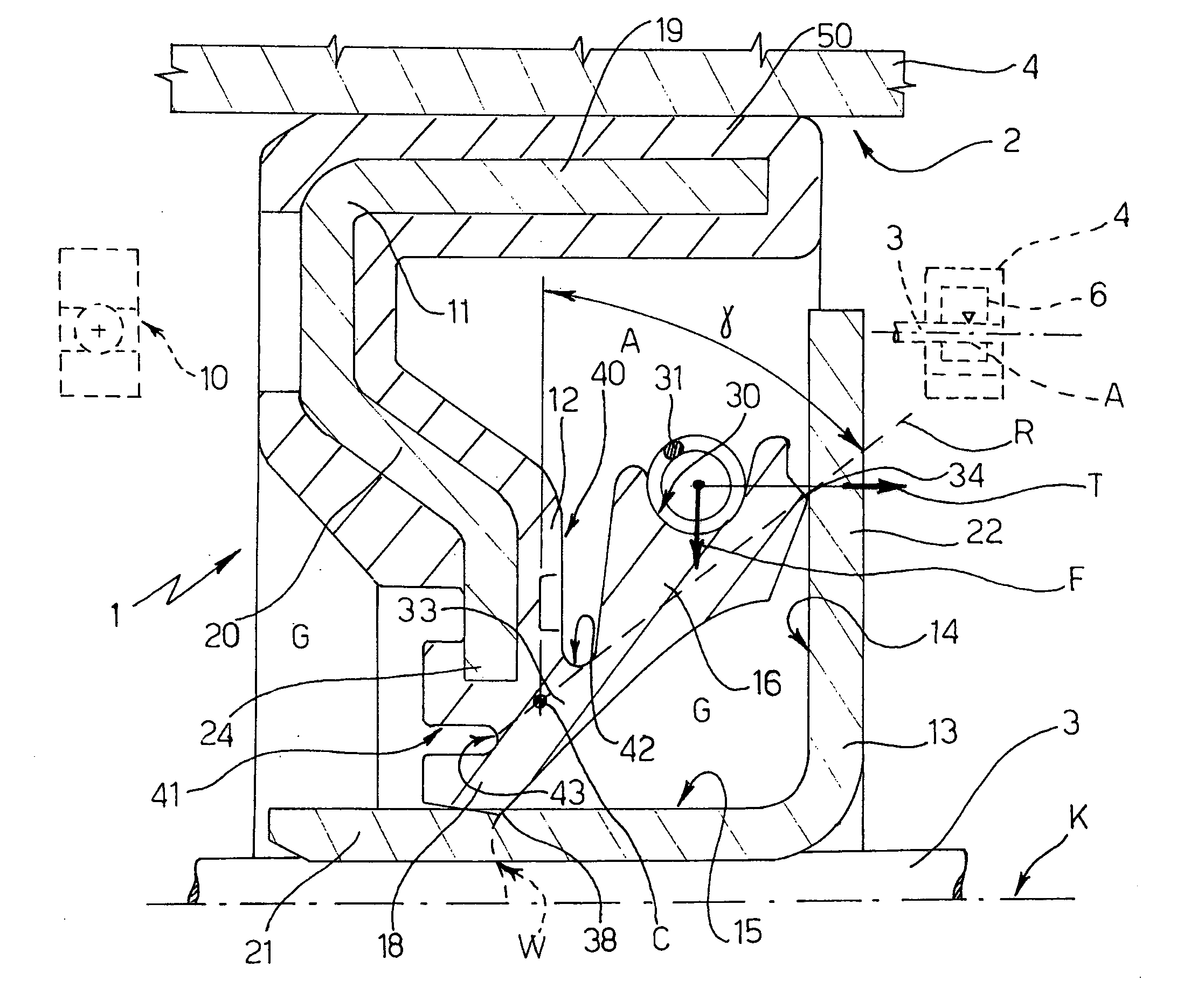
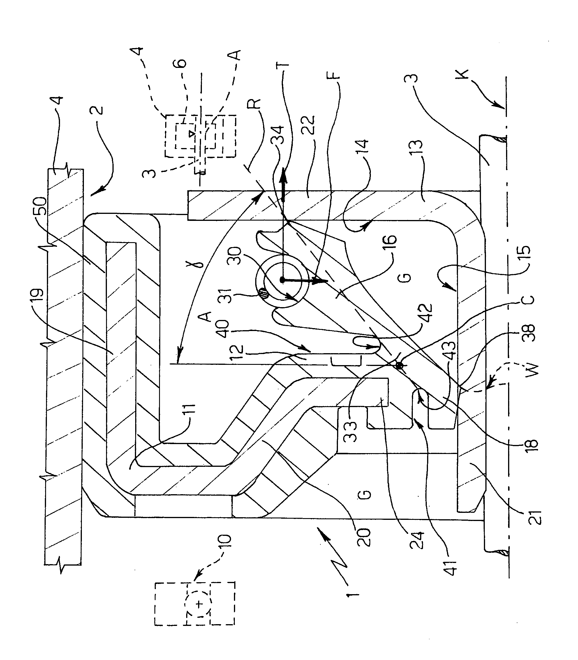
[0016]Number 1 in the accompanying drawing indicates a seal assembly, for an electric household appliance, insertable inside a gap 2 defined between two relatively rotating members 3, 4, between which a wash fluid, indicated A, is present in use.

[0017]With reference to the dash-line diagram on the right in the drawing, seal assembly 1 is designed, according to the invention, for use in a washing machine (not shown), and for insertion between a wash tub 4—housing a rotating laundry drum 6—and a shaft 3, which rotates with respect to tub 4, is partly immersed, in use, in the wash fluid A filling tub 4, and supports drum 6 in projecting manner through an opening formed in the rear wall of tub 4 and defining gap 2 to be sealed, in use, by seal assembly 1.

[0018]Gap 2, or a gap immediately adjacent to it, e.g. in a supporting structure of drum 6, also houses at least one known rolling bearing 10 supporting shaft 3, and which normally operates immersed in a lubricating fluid G, e.g. minera...


PUM


Abstract

A seal assembly including a first rigid shield having an annular sealing member of elastomeric material, and a second rigid shield mounted facing the first and having respective sliding surfaces for a first and second annular sealing lip of the annular sealing member, which extend towards the second rigid shield to exert axial sealing pressure and radial sealing pressure, respectively; wherein the first annular sealing lip has a radial seat facing the opposite way to the second annular sealing lip and housing a toroidal spring, which exerts a radial thrust on the first annular sealing lip eccentrically with respect to an elastic hinge defined by a root portion common to the first and second annular sealing lip, and having a centre of rotation located along a line extending through a V-shaped sealing edge of the first annular sealing lip and forming a 20° to 60° angle with a radial plane; the root portion being defined between two opposite annular recesses of the annular sealing member, which have a U-shaped radial section and bottom walls facing each other and substantially aligned along the aforementioned line; and the second annular sealing lip having a V-shaped sealing edge defined by an undulated, circumferential groove.

Description

[0001]The present invention relates to an annular seal assembly for a device comprising two relatively rotatable members such as a water pump or an electric household appliance, in particular for assembly to a washing machine drum drive shaft, to provide sealing between two relatively rotating members defined by the shaft itself and the wash tub in which the drum rotates, to prevent leakage of a wash fluid from the tub, on the one hand, and, on the other, to protect a bearing of the drum drive shaft from infiltration by water, while at the same time ensuring optimum sealing with a minimum amount of friction and noise.BACKGROUND OF THE INVENTION[0002]EP 1514966A1 provides numerous seal assembly solutions for preventing water leakage from the tub at the through seat for the drive shaft of the drum, and for protecting the bearings of the drum shaft. In all these solutions, the sealing assemblies have one or more sealing lips, and provide for exclusively radial sealing directly on the d...

Claims


Application Information

Patent Timeline
IPC IPC(8): F16J15/00
CPCD06F37/00F16J15/3264
Inventor FOTI, CLAUDIO
Owner AB SKF
Why Eureka
Try Eureka