
Solid-state hydrogen storage media and catalytic hydrogen recharging thereof

a hydrogen storage media and solid-state technology, applied in the direction of physical/chemical process catalysts, cell components, other chemical processes, etc., can solve the problems of more conventional hydrogen storage technologies, skin damage, and ill-suited mobile applications such as passenger vehicles, and achieve the effect of reducing the cost of owning and operating

Active Publication Date: 2008-11-06
INDIANA UNIV RES & TECH CORP
View PDF9 Cites 21 Cited by
  • Summary
  • Abstract
  • Description
  • Claims
  • Application Information

AI Technical Summary

Benefits of technology

[0005]The present invention provides a solid-state hydrogen storage material and a process for making a solid-state hydrogen storage material more thoroughly rechargeable. The process of this invention is believed capable of achieving a full or nearly-full recharge, thereby reducing the cost of owning and operating a hydrogen storage system and making the use of such storage systems practical for use in a wide variety of applications, including but not limited to powering fuel cells for vehicles, stationary power systems, and consumer electronics, and non-power applications including chemical production.
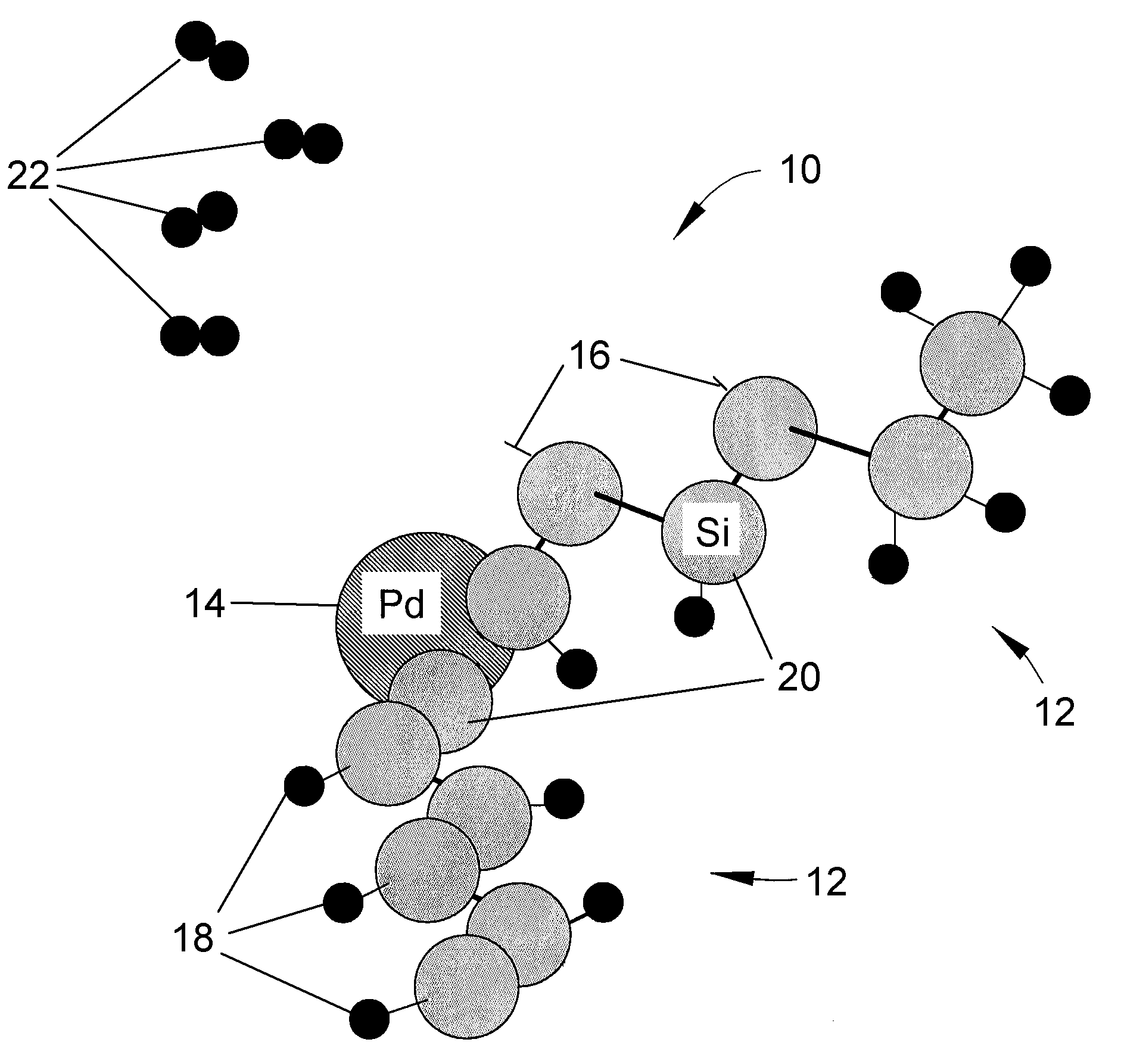
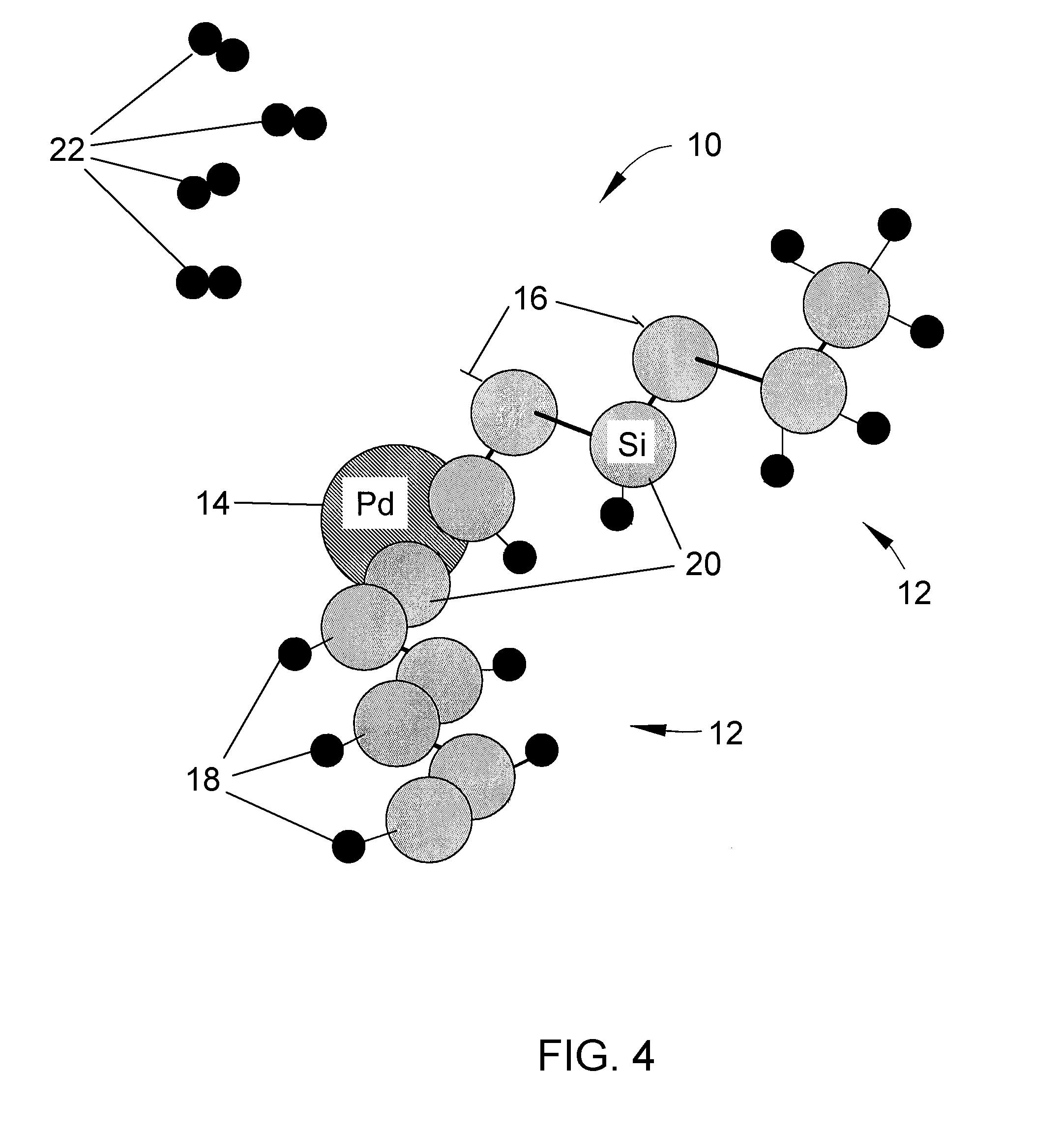
[0008]The storage material and process of the present invention address various factors that have previously been impediments to solid-state hydrogen storage media. First, the invention addresses dangling bond recombination, which poses a significant loss of recharge capacity for solid-state hydrogen storage materials. Recognizing that gaseous recharge with molecular hydrogen (H2) is insufficient to overcome the recombined dangling bond energy of silicon (and other potential storage media materials), the present invention provides a process in which a catalyst is not limited to enhancing the activation energy of a storage material. Instead, the process of this invention employs a catalyst to inhibit reforming of silicon dangling bonds after dehydrogenation that would result in silicon-to-silicon bonds and reduce the number of bond sites available to participate in hydrogen storage. As such, the catalyst is able to preserve bond sites for hydrogen bonding during subsequent rehydrogenation. Through the use of a catalyst in this manner, a solid-state hydrogen storage material can be potentially made at lower cost and weight and processed and operated at lower temperatures compared to the prior art. As such, the present invention is capable of significantly increasing the practicality, functionality and economics of solid-state hydrogen storage systems.

Problems solved by technology

However, more conventional hydrogen storage technologies suffer from significant drawbacks that make them ill-suited for mobile applications such as passenger vehicles.
For example, compressed hydrogen gas requires heavy tanks and very high pressures that would pose a potential hazard in a crash, and liquified hydrogen can cause skin damage if released and requires active refrigeration that is energy-intensive and requires considerable insulation.
A complication with the use of silicon as a hydrogen storage media is the tendency for silicon to reform upon dehydrogenation.
In other words, once hydrogen atoms leave the silicon atoms to which they are bonded, the remaining silicon dangling bonds reconnect with their neighbors through silicon-to-silicon bonding, making a substantial fraction of the original bond sites no longer available to participate in hydrogen storage.
Such low recharge capabilities render gaseous recharging of solid-state hydrogen storage systems impractical for vehicular and many other applications, and consequently necessitates recharging by aqueous methods.

Method used


Image

  • Solid-state hydrogen storage media and catalytic hydrogen recharging thereof
  • Solid-state hydrogen storage media and catalytic hydrogen recharging thereof
  • Solid-state hydrogen storage media and catalytic hydrogen recharging thereof

Examples


Embodiment Construction

[0014]The present invention describes a process and solid-state storage material with which full or nearly-full recharging can be attained for hydrogen onto the material. The invention addresses problems resulting from dangling bonds of a storage material reforming upon dehydrogenation, making fewer sites available for subsequent hydrogen storage (recharging). The present invention overcomes these problems by treating the storage material to remove those hydrogen atoms that are least energetically bonded to atoms of the storage material, and thereby intentionally create sites with dangling bonds, while not removing hydrogen atoms that are more energetically bonded to atoms of the storage material. A catalyst is then introduced into the storage material that molecularly bonds with the dangling bonds, after which hydrogen recharging can be repeatedly performed without significantly loss of hydrogen bonding sites within the storage material. Furthermore, recharging can be performed wit...


PUM

PropertyMeasurementUnit
Temperatureaaaaaaaaaa
Timeaaaaaaaaaa
Energyaaaaaaaaaa

Abstract

A solid-state hydrogen storage material and process for making the material more thoroughly rechargeable. The process entails forming a porous matrix material to contain atoms of a first element and hydrogen atoms, in which the atoms of the first element are capable of bonding with more than one hydrogen atom per atom of the first element, and the atoms of the first element are molecularly arranged within the porous matrix material so that different atoms of the first element are bonded to different numbers of hydrogen atoms at correspondingly different levels of bonding energy. At least some of the hydrogen atoms bonded to the atoms of the first element at the lowest bond energies are then removed without removing hydrogen atoms bonded at higher bond energies, after which atoms of a second element are bonded to those atoms of the first element from which hydrogen atoms were removed.

Description

BACKGROUND OF THE INVENTION[0001]The present invention generally relates to hydrogen storage systems and methods. More particularly, this invention relates to a system and method for recharging a porous hydrogen storage media through the use of a catalyst, and by which up to almost 100% of the original quantity of hydrogen stored in the media can be replenished.[0002]Hydrogen fuel cells are being considered for a wide variety of power applications, including but not limited to mobile applications such as vehicles. However, more conventional hydrogen storage technologies suffer from significant drawbacks that make them ill-suited for mobile applications such as passenger vehicles. For example, compressed hydrogen gas requires heavy tanks and very high pressures that would pose a potential hazard in a crash, and liquified hydrogen can cause skin damage if released and requires active refrigeration that is energy-intensive and requires considerable insulation. Hydrogen storage for vehi...

Claims


Application Information

Patent Timeline
IPC IPC(8): B01J20/16B01J20/08B01J20/18B01J20/10
CPCC01B3/001B01J20/02Y02E60/324B01J20/0259B01J20/08B01J20/18B01J20/20Y02E60/32
Inventor SCHUBERT, PETER JAMES
Owner INDIANA UNIV RES & TECH CORP
Learn More