Electrostatic Chuck, Manufacturing method thereof and substrate treating apparatus

a manufacturing method and electrostatic chuck technology, applied in electrical devices, liquid surface applicators, coatings, etc., can solve the problems of particle contamination, poor heat transference, adversely affecting the quality of workpieces,

Inactive Publication Date: 2008-11-13
TOTO LTD
View PDF0 Cites 35 Cited by
  • Summary
  • Abstract
  • Description
  • Claims
  • Application Information

AI Technical Summary

Problems solved by technology

The plasma processing apparatus including an electrostatic chuck may damage the surface of the electrostatic chuck by plasma exposure, and adversely affect the quality of the workpiece due to particles resulting from plasma-induced erosion.
However, when sputtering is used to integrally form a member having a mounting surface from a material such as yttrium oxide, large-sized particles may drop off, causing particle contam...

Method used


Image

  • Electrostatic Chuck, Manufacturing method thereof and substrate treating apparatus
  • Electrostatic Chuck, Manufacturing method thereof and substrate treating apparatus
  • Electrostatic Chuck, Manufacturing method thereof and substrate treating apparatus

Examples


first embodiment

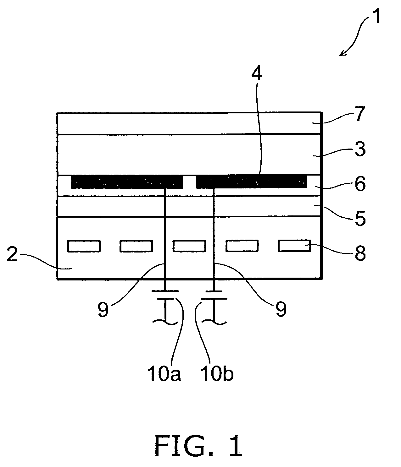
[0044]FIG. 1 is a schematic view for illustrating an electrostatic chuck according to the invention.

[0045]As shown in FIG. 1, the electrostatic chuck 1 includes a base 2, a dielectric substrate 3, and electrodes 4.

[0046]An insulator film 5 made of an inorganic material is formed on one major surface (the surface on the electrode 4 side) of the base 2. A polycrystalline structure 7 made of a brittle material is formed by aerosol deposition on one major surface (on the mounting surface side) of the dielectric substrate 3, and the electrodes 4 are formed on the other major surface of the dielectric substrate 3.

[0047]That is, a polycrystalline structure 7 is formed by aerosol deposition on the major surface of a member (dielectric substrate 3) provided with the electrodes 4.

[0048]The upper surface of the polycrystalline structure 7 serves as a mounting surface of a workpiece such as a semiconductor wafer. The major surface with the electrodes 4 provided thereon and the major surface wit...

second embodiment

[0131]FIG. 11 is a schematic view for illustrating an electrostatic chuck according to the invention.

[0132]The same elements as those described with reference to FIG. 1 are marked with like reference numerals, and the description thereof is omitted.

[0133]As shown in FIG. 11, the electrostatic chuck 30 includes a dielectric substrate 3. A polycrystalline structure 7 made of a brittle material is formed by aerosol deposition on one major surface (on the mounting surface side) of the dielectric substrate 3. Furthermore, protrusions 32 are formed on the surface (on the mounting surface side) of the polycrystalline structure 7. The upper surface of the protrusions 32 serves as a mounting surface of a workpiece such as a semiconductor wafer.

[0134]The material and shape of the protrusion 32 are described later.

[0135]A through hole 31 is provided to run through the center of the electrostatic chuck 30. One end of the through hole 31 opens to the upper surface of the polycrystalline structur...


PUM


Abstract

An electrostatic chuck includes: a mounting surface on which a workpiece is to be mounted, the mounting surface including a polycrystalline structure formed by aerosol deposition, the polycrystalline structure having a protrusion on its surface. At least the protrusion contains yttria (Y2O3).

Description

CROSS-REFERENCE TO RELATED APPLICATIONS[0001]This application is based upon and claims the benefit of priorities from the prior Japanese Patent Application No. 2006-321900, filed on Nov. 29, 2006, and the prior Japanese Patent Application No. 2007-306648, filed on Nov. 27, 2007; the entire contents of which are incorporated herein by reference.BACKGROUND OF THE INVENTION[0002]1. Field of the Invention[0003]This invention relates to an electrostatic chuck, a method for manufacturing an electrostatic chuck, and a substrate processing apparatus.[0004]2. Background Art[0005]A substrate processing apparatus for performing etching, CVD (chemical vapor deposition), sputtering, ion implantation, ashing, exposure, and inspection includes an electrostatic chuck as a means for attracting and holding a workpiece such as a semiconductor substrate and a glass substrate.[0006]A plasma processing apparatus is one type of this substrate processing apparatus. The plasma processing apparatus including...

Claims


Application Information

Patent Timeline
IPC IPC(8): B05C13/00B05D5/12
CPCH01L21/6831
Inventor NISHIMIZU, RYOICHIHATONO, HIRONORIMATSUMURA, AKIHIKO
Owner TOTO LTD
Why Eureka
Try Eureka