Magnetic resonance imaging apparatus and control method thereof

a magnetic resonance imaging and magnetic resonance technology, applied in the field of magnetic resonance imaging apparatus, can solve the problems of insufficient spatial resolution, inability to terminate examination, and long imaging tim

Active Publication Date: 2008-11-13
TOSHIBA MEDICAL SYST CORP
View PDF69 Cites 23 Cited by
  • Summary
  • Abstract
  • Description
  • Claims
  • Application Information

AI Technical Summary

Benefits of technology

[0019]Under the circumstances, appropriately giving aid so that the subject c...

Problems solved by technology

In case of whole heart MR coronary angiography (WH MRCA) where a course of a coronary artery of an entire heart is imaged in particular, holding a breath may lead to an insufficient spatial resolution in some cases.
However, when the respiratory level is not fixed and gradually lowered or gradually increased and a portion of the signal obtained by subjecting the NMR signal to one-dimensional Fourier transformation that corresponds to a position of the diaphragm deviates from the allowable range as shown in, e.g., FIG. 3, an imaging time may become long, or an examination may not be terminated in the worst case.
However, even if the abdominal belt 500 is used to fix the abdominal, the respiratory motion cannot be completely suppressed, and the respiratory level may fluctuate to prolong an examination time in long-time imaging.
When the examination is prolonged, the subject may start moving because of discomfort caused by fixing.
Moreover, when the subject has a large body, even the abdominal belt cannot be used.
However, it is hard for the subject to correctly understand his or her respiratory level.
In such a case, data is not collected even though the subject is holding breath, which imposes a load on the subject.
It should be noted that the inadequate breath holding state lengthens a period where data cannot be collected, and an efficiency for data collection may be lowered, resulting in a long examination time.
Additionally,...

Method used


Image

  • Magnetic resonance imaging apparatus and control method thereof
  • Magnetic resonance imaging apparatus and control method thereof
  • Magnetic resonance imaging apparatus and control method thereof

Examples


first embodiment

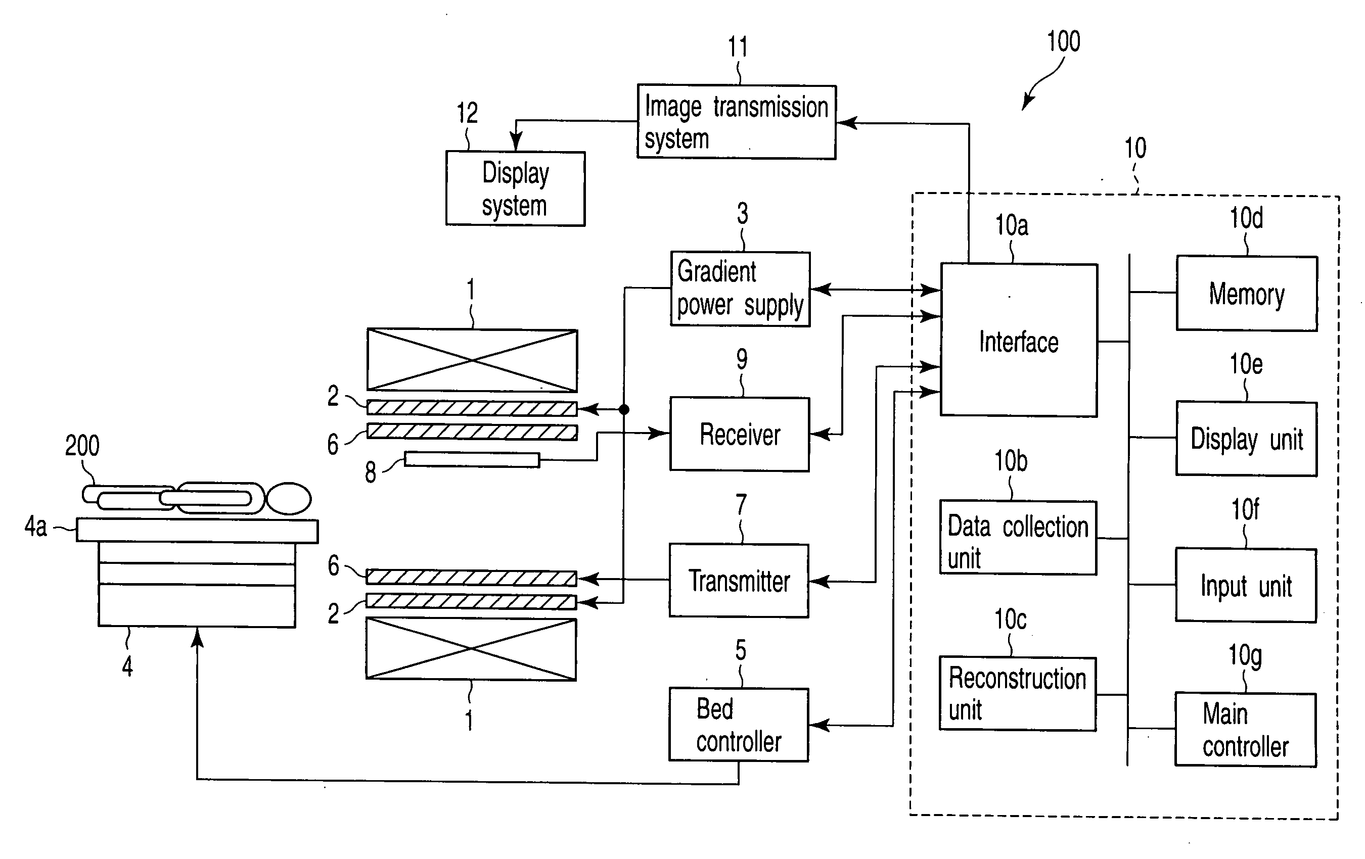
[0069]FIG. 9 shows the configuration of a magnetic resonance imaging (MRI) apparatus, generally indicated at 100, according to a first embodiment. The MRI apparatus 100 includes a static field magnet 1, a gradient coil 2, a gradient power supply 3, a bed 4, a bed controller 5, a transmission RF coil 6, a transmitter 7, a receiving RF coil 8, a receiver 9, a computer system 10, a image transmission system 11 and a display system 12.

[0070]The static field magnet 1 is formed in the shape of a hollow cylinder and adapted to generate a uniform static magnetic field within its inside shape. As the static field magnet 1 use is made of a permanent magnet, a superconducting magnet, or the like.

[0071]The gradient coil 2 is formed in the shape of a hollow cylinder and placed inside the static field magnet 1. The gradient coil 2 is a combination of three coils each corresponding to a respective one of the three mutually orthogonal X, Y and Z axes. When the three coils are individually supplied ...

fourth embodiments

Second to Fourth Embodiments

[0106]Meanwhile, in the first embodiment, collection of the NMR signal for acquisition of positional information is performed only once per heart rate. That is, the respiratory level is monitored only once or twice per respiration as shown in FIG. 30, the subject may not recognize a change in respiration even if the subject is informed of the monitored respiratory level alone. That is, a interval of updating information acquired in the above-explained cycle may be too long as a interval of updating information required to control the respiratory level. In other words, a feedback time constant in respiratory level control is long.

[0107]Under such circumstances, it can be considered that adjustment of the respiratory level by the subject based on the monitored respiratory level is similar to a case where the feedback time constant in automatic control is long, and under-control or over-control may possibly occur.

[0108]Thus, second to fourth embodiments that...

second embodiment

[0113]A main controller 10g in the second embodiment includes a plurality of functions mentioned below. It is to be noted that the plurality of functions can be realized by allowing a processor included in the main controller 10g to execute a program.

[0114]As one of the functions, each relevant section is controlled to enable a data collection unit 10b to obtain an NMR signal required to detect a respiratory level of the subject 200 (which will be referred to as a monitoring NMR signal hereinafter). As one of the functions, the respiratory level of the subject 200 is detected based on the monitoring NMR signal acquired by the data collection unit 10b. As one of the functions, each relevant section is controlled to enable the data collection unit 10b to collect an NMR signal required to reconstruct an image (which will be referred to as a reconstruction NMR signal hereinafter) when the respiratory level detected based on the monitoring NMR signal falls within an allowable range. As o...


PUM


Abstract

A magnetic resonance imaging apparatus includes a collection unit which applies a uniform static magnetic field to a subject and also applies a radio-frequency magnetic field and a gradient magnetic field to the subject in accordance with a predetermined pulse sequence to collect a magnetic resonance signal from the subject, a imaging unit which images the subject based on the magnetic resonance signal collected by the collection unit, a detection unit which detects a respiratory level of the subject, an informing unit which informs the subject of whether the detected respiratory level falls within an allowable range, and a unit which controls the collection unit and the imaging unit in such a manner that the magnetic resonance signal for imaging is collected and the subject is imaged based on the thus collected magnetic resonance signal for imaging when the detected respiratory level falls within the allowable range.

Description

CROSS-REFERENCE TO RELATED APPLICATIONS[0001]This application is based upon and claims the benefit of priority from prior Japanese Patent Applications No. 2007-122737, filed May 7, 2007; and No. 2008-018232, filed Jan. 29, 2008, the entire contents of both of which are incorporated herein by reference.BACKGROUND OF THE INVENTION[0002]1. Field of the Invention[0003]The present invention relates to a magnetic resonance imaging apparatus that obtains an image of a subject based on a nuclear magnetic resonance (NMR) signal emitted from the subject, and a control method thereof.[0004]2. Description of the Related Art[0005]To image a coronary artery based on the magnetic resonance image (MRI) method, a method of using a three-dimensional (3D) steady-state free precession (SSFP) sequence to perform imaging in a breath holding state or a voluntary breathing state is used. In case of whole heart MR coronary angiography (WH MRCA) where a course of a coronary artery of an entire heart is image...

Claims


Application Information

Patent Timeline
IPC IPC(8): A61B5/055
CPCA61B5/055A61B5/7285G01R33/283G01R33/563A61B6/541G01R33/56509G01R33/5676A61B5/7207G01R33/5635
Inventor KUHARA, SHIGEHIDE
Owner TOSHIBA MEDICAL SYST CORP
Why Eureka
Try Eureka