Fabrication process and package design for use in a micro-machined seismometer or other device

a seismometer and micro-machine technology, applied in the field of seismometers, can solve the problems of not having a prior art for self-aligning solder balls directly on the substrate to be bonded, design for a maximum thermal isolation device utilizing a minimum of substrate area, and maximizing mechanical rigidity, so as to prevent flexural elements and general applicability to other mems sensors

Inactive Publication Date: 2008-11-20
KINEMETRICS
View PDF10 Cites 29 Cited by
  • Summary
  • Abstract
  • Description
  • Claims
  • Application Information

AI Technical Summary

Benefits of technology

[0033]Finally the system can be modified further by measuring the temperature variations externally to the device the temperature of the inner frame can be actively controlled by using a control loop (preferably digital due to the extremely long periods required) and heat generating resistors on the frame to prevent the flexural elements seeing the external temperature variations. These packaging techniques and thermal control methodologies, both passive and active have general applicability to other MEMS sensors.

Problems solved by technology

Furthermore, there is no prior art for self-aligning the solder balls directly on the substrate to be bonded.
However, the design for a device that provides maximum thermal isolation utilizing a minimum of substrate area, and maximizing mechanical rigidity, has not been presented.

Method used


Image

  • Fabrication process and package design for use in a micro-machined seismometer or other device
  • Fabrication process and package design for use in a micro-machined seismometer or other device
  • Fabrication process and package design for use in a micro-machined seismometer or other device

Examples


Embodiment Construction

[0052]As explained earlier, U.S. Pat. No. 6,776,042 entitled “MICRO-MACHINED ACCELEROMETER” discloses an improved micro-machined suspension plate which may be utilized in an accelerometer, seismometer (velocimeter) and / or other similar device. The subsequent U.S. patent application Ser. No. 10 / 851,029 entitled “IMPROVED MICRO-MACHINED SUSPENSION PLATE WITH INTEGRAL PROOF MASS FOR USE IN A SEISMOMETER OR OTHER DEVICE” discloses improvements to the basic design of the suspension plate.

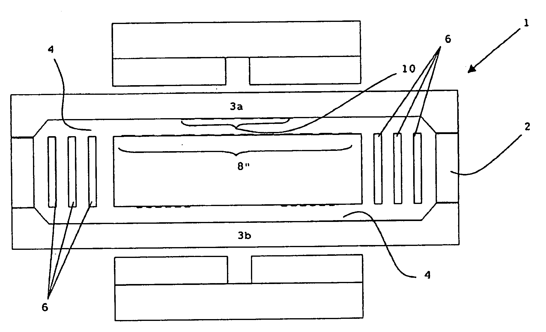
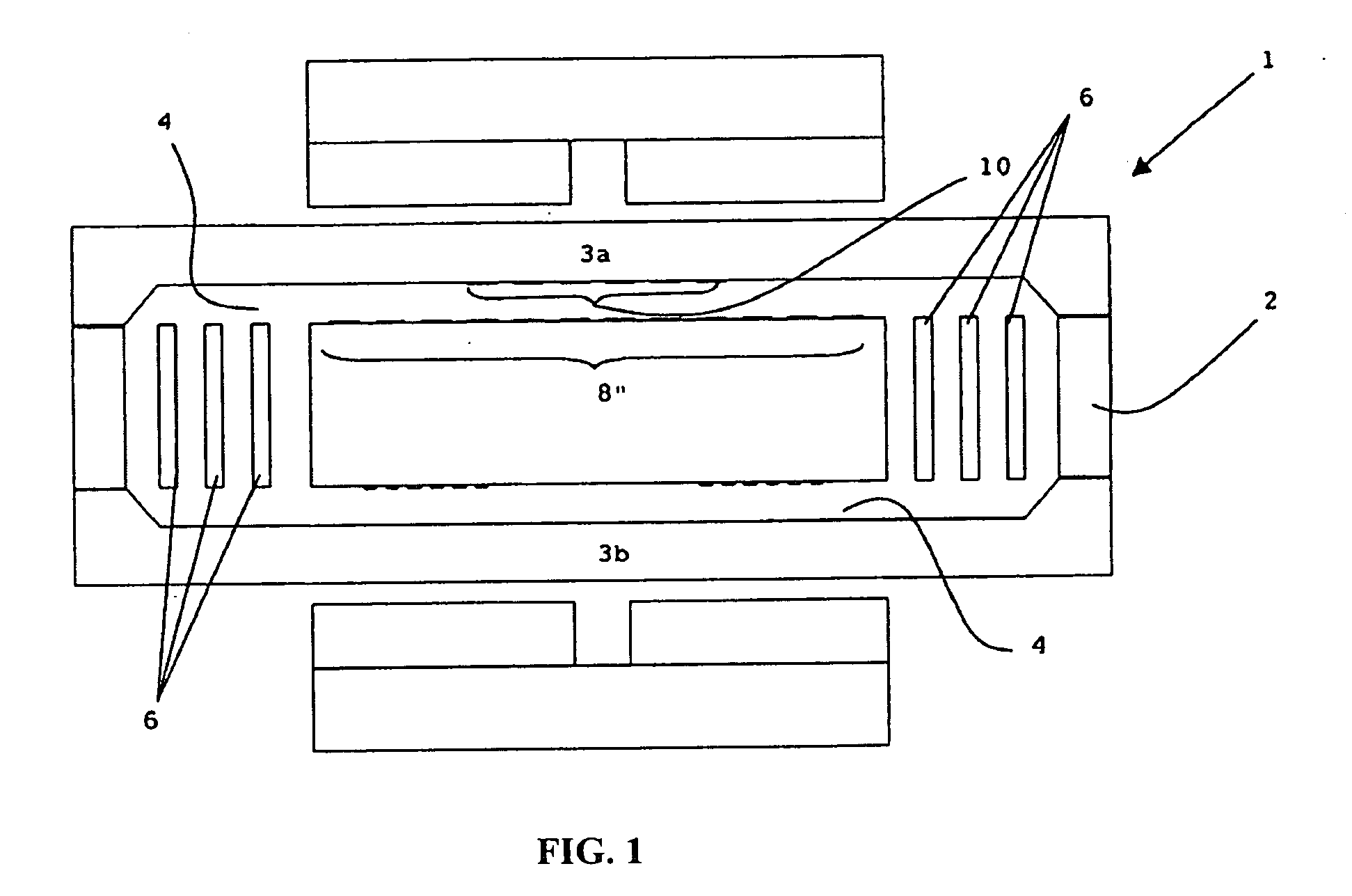
[0053]The suspension plate of the '029 application is formed of and includes a revolutionary, in-plane suspension geometry rather than a traditional—spring design. More particularly, the suspension plate is micro-machined to form a central proof mass and flexural elements located on opposite sides of the proof mass. FIG. 1 illustrates a cross-sectional diagram of a seismometer 1 having a suspension plate 2 and two capacitive plates 3a-b (alternatively, the device can have one capacitive plate), with a ce...


PUM

PropertyMeasurementUnit
Galperin angleaaaaaaaaaa
distanceaaaaaaaaaa
resonant frequencyaaaaaaaaaa

Abstract

An accelerometer or a seismometer using an in-plane suspension geometry having a suspension plate and at least one fixed capacitive plate. The suspension plate is formed from a single piece and includes an external frame, a pair of flexural elements, and an integrated proof mass between the flexures. The flexural elements allow the proof mass to move in the sensitive direction in the plane of suspension while restricting movement in all off-axis directions. Off-axis motion of the proof mass is minimized by the use of intermediate frames disbursed within and between the flexural elements. Intermediate frames can include motion stops to prevent further relative motion during overload conditions. The device can also include a dampening structure, such as a spring or gas structure that includes a trapezoidal piston and corresponding cylinder, to provide damping during non-powered states. The capacitive plate is made of insulating material. A new method of soldering the capacitive plate to the suspension plate is also disclosed.

Description

PRIORITY CLAIM[0001]This application is a continuation-in-part of a prior co-pending application Ser. No. 10 / 851,029 entitled “IMPROVED MICRO-MACHINED SUSPENSION PLATE WITH INTEGRAL PROOF MASS FOR USE IN A SEISMOMETER OR OTHER DEVICE” filed on May 21, 2004, which is a continuation-in-part of application Ser. No. 10 / 058,210, filed on Jan. 25, 2002, now a U.S. Pat. No. 6,776,042.INCORPORATION BY REFERENCE[0002]This Application specifically incorporates by reference the subject matter and complete text of the related U.S. Pat. No. 6,776,042 entitled “MICRO-MACHINED ACCELEROMETER”.FIELD OF THE INVENTION[0003]The invention relates to seismic instrumentation in general. More particularly, the invention is related to improved fabrication and packaging techniques for a micro-machined suspension plate having an integral proof mass and a method of fabrication for the same that may be utilized in a seismometer (velocimeter), an accelerometer, or other similar device.DESCRIPTION OF THE PRIOR AR...

Claims


Application Information

Patent Timeline
Patent Type & Authority Applications(United States)
IPC IPC(8): G01P15/125H05K3/34
CPCG01P15/08G01P15/0802G01P15/125Y10T29/49144G01P15/132G01V1/181G01P2015/0814G01P15/131G01P2015/082Y10T29/49002G01V1/18G01V13/00
Inventor PIKE, WILLIAM T.STANDLEY, IAN
Owner KINEMETRICS
Why Eureka
Try Eureka