
Light scattering detector

a detector and light scattering technology, applied in the field of light scattering detectors, can solve the problems of reducing the accuracy of measuring ultrafine particles with a diameter of less than 10 nm, difficult or impossible separation of components by liquid chromatography, and large molecular weight, and achieves simple measurement operation, improved accuracy, and elimination of dynamic light scattering measurement results.

Inactive Publication Date: 2008-11-20
SHIMADZU CORP
View PDF11 Cites 42 Cited by
  • Summary
  • Abstract
  • Description
  • Claims
  • Application Information

AI Technical Summary

Benefits of technology

The present invention provides a light scattering detector that can obtain information on the molecular weight, size, or other data of particles with high accuracy in a single measurement. The detector includes a sample cell for holding a sample, two light sources emitting different wavelengths or ranges of wavelengths, an incident light switcher for time-divisionally irradiating the sample cell with both static and dynamic light scattering measurement lights, and a mathematical processor for separating the detection signals and performing both static and dynamic light scattering methods simultaneously. The detector can measure the scattered light from the sample in response to the static and dynamic light scattering measurements, and the detection signals can be separated to be detected. The invention solves the problem of previous light scattering detectors that could only measure one type of scattered light and had limited accuracy in measuring particles of different sizes.

Problems solved by technology

In general, components having large molecular weights, insoluble polymers or microscopic particles, are difficult or impossible to separate by liquid chromatography.
However, the accuracy reduces when measuring ultrafine particles with a diameter of less than 10 nm, and the measurement time becomes longer since the calculation becomes more complicated.
Therefore, in the case when the diameters of the particles to be measured vary from small to large, as in the case when measuring a sample whose component was separated as time progresses by a chromatograph or other devices, small size particles are not likely to be detected when the device is set to perform a static light scattering measurement.
On the other hand, large size particles are not likely to be detected when the device is set to perform a dynamic light scattering measurement.
This makes an operation troublesome, and also causes the problem that it is difficult to enhance the measurement accuracy because GPC or FFF cannot always be performed under the very same condition.
Problems of missing large size or small size particles are also caused when the size of the particles in a liquid sample change drastically and quickly as time progresses because of, for example, a reaction, binding, or condensation, such as a condensation or association of protein or protein folding.
In addition, one cannot tell which is suitable a static light scattering method or a dynamic light scattering method for measuring a liquid sample in which particles whose diameters are unknown are dispersed until a measurement is once carried out with either of the measurement methods and the result is obtained.
Therefore, if a measurement is performed with either of the measurement methods and the method turns out to be inappropriate, the same sample needs to be measured again with the other measurement method.
This makes an operation troublesome, and it may be possible that the proper result cannot be obtained if a re-measurement is difficult to be performed for the reason that the sample is valuable or scarce.

Method used


Image

  • Light scattering detector
  • Light scattering detector
  • Light scattering detector

Examples


Embodiment Construction

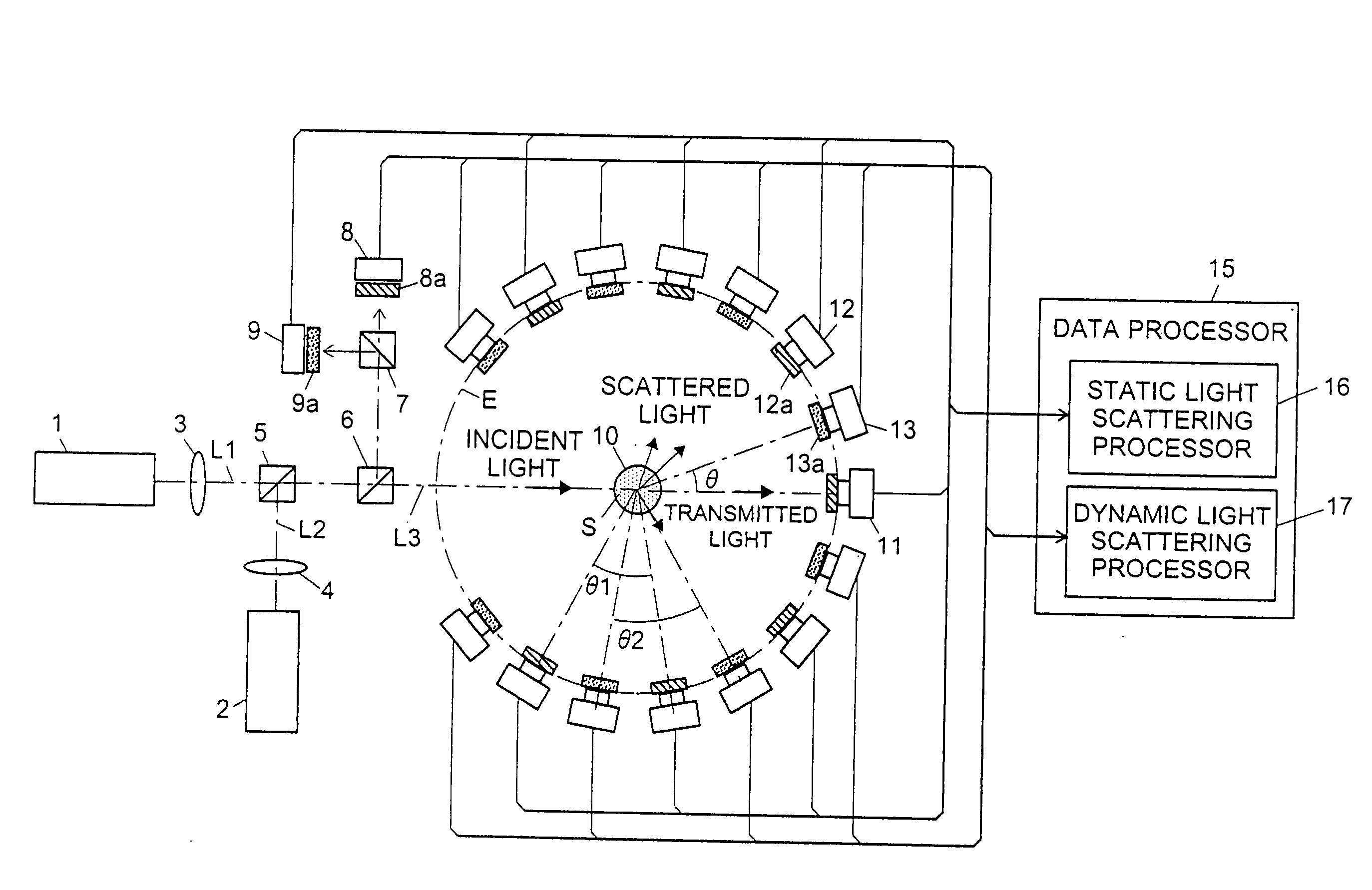
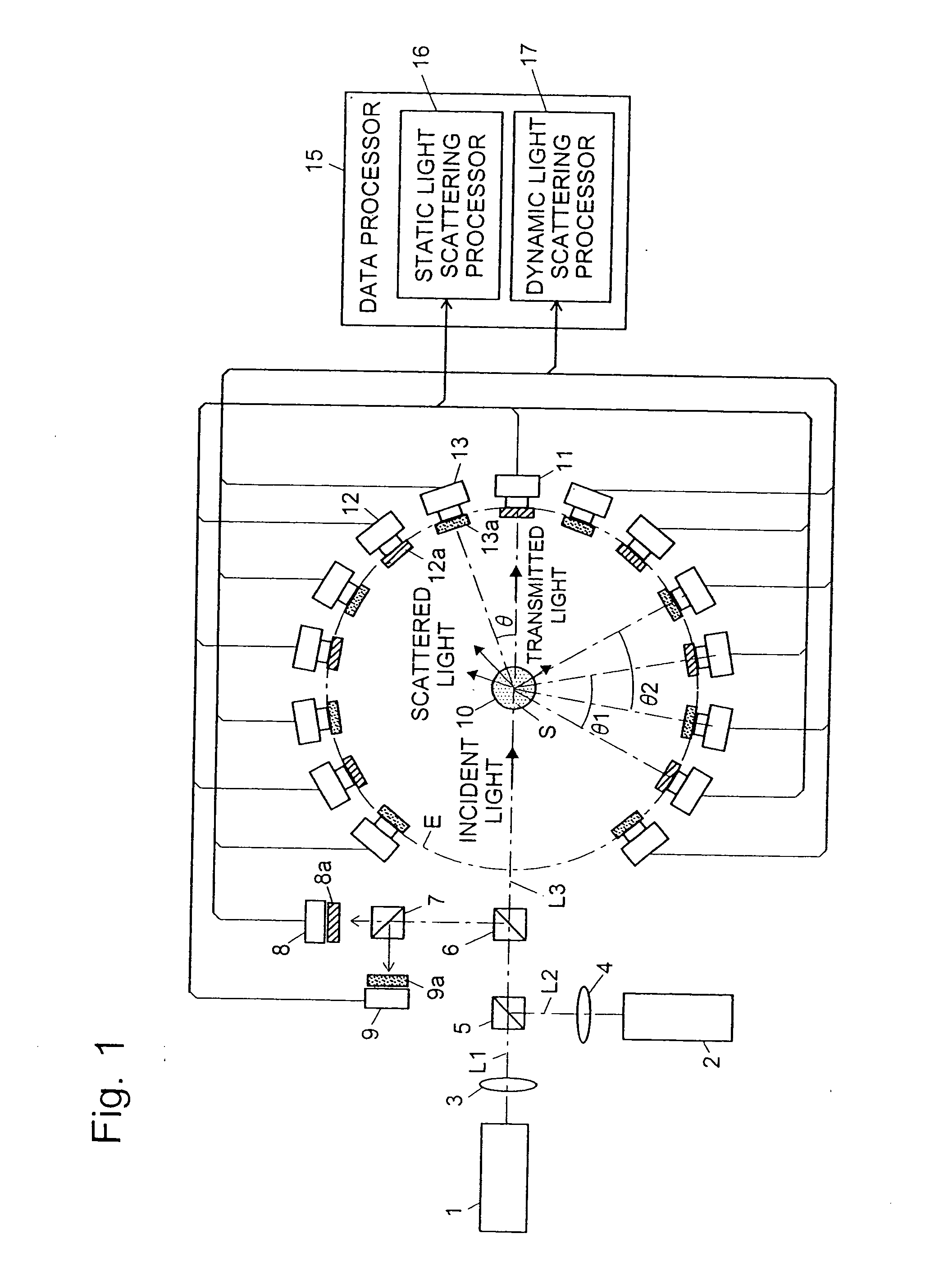
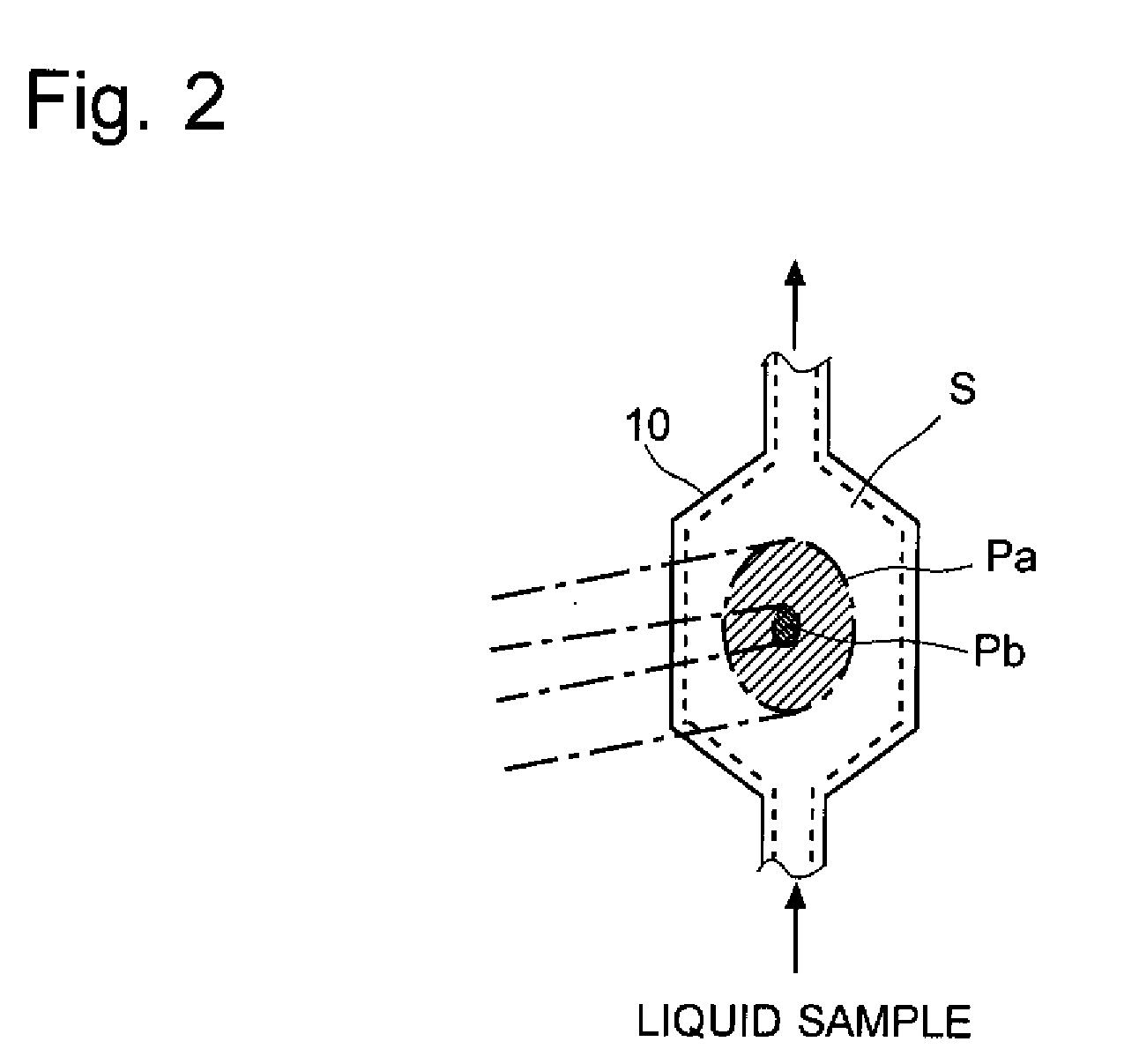
[0066]First, a hybrid light scattering detector which is an embodiment of the light scattering detector of the first aspect of the invention is described with reference to figures. FIG. 1 is an overall block diagram of a hybrid light scattering detector of this embodiment and FIG. 2 shows a state of an incident light in the sample cell.

[0067]In the hybrid light scattering detector of this embodiment, a sample cell 10 is placed at the center of the circle E. The sample cell 10 is a flow cell for providing the liquid sample S thereto with transparent walls. (As the sample cell 10, other cells for containing a liquid sample such as a square cell and a test-tube cell may be alternatively used.) On the circle E, a transmitted light detector 11, a plurality of static light scattering detectors, and a plurality of dynamic light scattering detectors are placed around the sample cell 10. The plural static light scattering detectors 12 are placed with a predetermined angular interval of θ1, a...


PUM

PropertyMeasurementUnit
diameteraaaaaaaaaa
light scatteringaaaaaaaaaa
first wavelengthaaaaaaaaaa

Abstract

The light scattering detector according to the present invention aims at simultaneously measuring the molecular weight and size of particles having varieties of diameters. This detector facilitates the measurement operation and knowing how particles associate or dissociate as time progresses. In this detector, the emitted light (static light scattering measurement light) having a first wavelength by the first light source and the emitted light (dynamic light scattering measurement light) having a second wavelength which is different from the first wavelength by the second light source are combined by a beam splitter 5 and coaxially directed onto the sample sell 10 to which a liquid sample S is supplied. While the irradiated area by the static light scattering measurement light is large, the irradiated area by the dynamic light scattering measurement light, which is coherent light, is narrow. Detectors 12 which selectively detect the first wavelength and detectors 13 which selectively detect the second wavelength are placed so as to encircle the sample cell 10. The detection signals by the detectors 11, 12 and the detection signals by the detectors 13 are separately mathematically-operated by a data processor 15 to calculate the molecule weight and size of the particles in the sample S.

Description

[0001]The present invention relates to a light scattering detector used for a microscopic-particle detector for measuring the molecular weight and size, e.g. turning radius, of microscopic particles dispersed in a liquid sample.BACKGROUND OF THE INVENTION[0002]In general, components having large molecular weights, insoluble polymers or microscopic particles, are difficult or impossible to separate by liquid chromatography. As methods for separating such substances, Gel Permeation Chromatography (abbreviated as GPC hereinafter) and Field Flow Fractionation (abbreviated as FFF hereinafter), for example, are known. And, as a detector of the microscopic particles separated by GPC or FFF, a multiangle light scattering detector is conventionally used, which is founded on the principle of a static light scattering method (see Patent Documents 1 and 2 for examples). The multiangle light scattering detector is able to simultaneously detect the lights coming out from a sample at plural differ...

Claims


Application Information

Patent Timeline
Patent Type & Authority Applications(United States)
IPC IPC(8): G01N21/51
CPCG01N15/0205G01N2015/0092G01N2015/0222
Inventor OHKUBO, KUNIHIKO
Owner SHIMADZU CORP
Learn More