
Dc-dc converter

Inactive Publication Date: 2008-11-20
SANKEN ELECTRIC CO LTD
View PDF5 Cites 2 Cited by
  • Summary
  • Abstract
  • Description
  • Claims
  • Application Information

AI Technical Summary

Benefits of technology

[0034]An object of the present invention is to provide a smaller-sized, lower-cost, and more highly-efficient DC-DC converter including a voltage supply circuit with multiple outputs having lower output voltages.
[0041]The present invention includes: the closed loop circuit constituted by the tightly coupled primary winding of the second transformer, the tightly coupled primary winding of the third transformer, and the second reactor; and a second series circuit in which the secondary windings of the second transformer and the secondary windings of the third transformer are connected in series to the both ends of the secondary winding of the first transformer. Thus, the present invention makes it possible to: cause the current flowing in each of the smoothing capacitors to be shaped like a rectangular wave; decrease each of the ripple currents flowing into each of the smoothing capacitors; reduce the capacity of each of the smoothing capacitors; and lessen the number of smoothing capacitors.
[0042]In addition, the relationship between the voltages respectively generated in the secondary windings of the first transformer and the output voltages is improved, as compared with that of the conventional circuit. As a result, the leakage inductance between the primary winding and the secondary winding of the first transformer can be used as the current resonance reactor. Thus, the present invention can provide a smaller-sized, lower-cost, and more highly-efficient DC-DC converter when the DC-DC converter includes a voltage supply circuit with multiple outputs having lower output voltages.

Problems solved by technology

As a result, the use of the leakage inductance between the primary winding and the secondary windings of the transformer T1 for the reactor Lr1 constituting the resonance circuit causes the following problem.
If the voltage supply circuit with a large output electric power is configured, then the number of turns needs to be decreased, thereby making it difficult to accurately select the turns ratio on the secondary winding side.
Nevertheless, these solutions also have problems that the cost is increased, and that a reduction of the number of turns for the secondary windings does not allow the turns ratio to be set accurately.
As a result, there is still a problem that any current solutions cannot deal with a voltage supply circuit with multiple outputs having lower output voltages.

Method used


Image

  • Dc-dc converter
  • Dc-dc converter
  • Dc-dc converter

Examples


embodiment 1

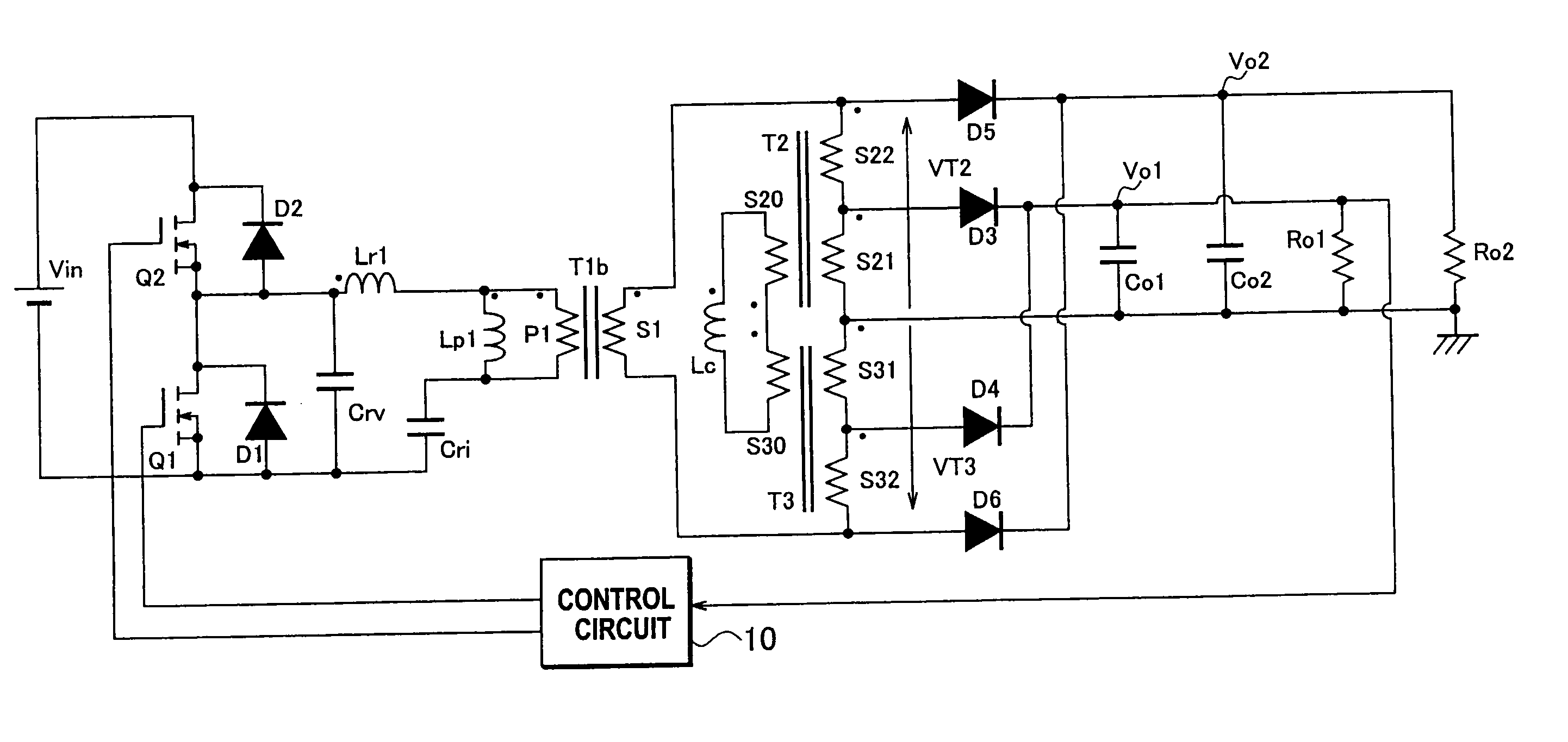
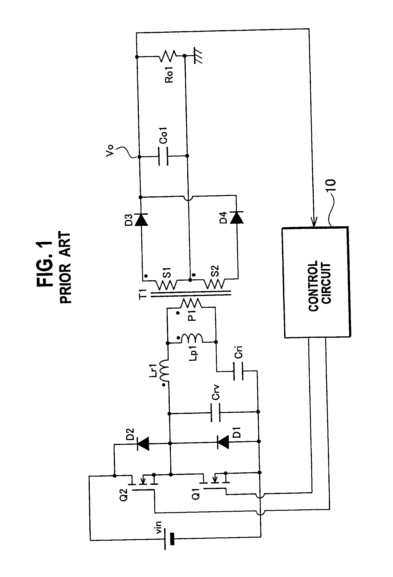
[0053]FIG. 4 is a block diagram of a circuit of a DC-DC converter according to embodiment 1 of the present invention. Like the DC-DC converter shown in FIG. 1, the DC-DC converter shown in FIG. 4 is configured by use of a half-bridge circuit.

[0054]A transformer (a first transformer) T1b includes a primary winding P1 and a secondary winding S1. Another transformer (a second transformer) T2 includes a coupled winding (a primary winding) S20 and transformer windings (secondary windings) S21 and S22, the three windings being tightly coupled with one another. Yet another transformer (a third transformer) T3 includes a coupled winding (a primary winding) S30 and transformer windings (secondary windings) S31 and S32, the three windings being tightly coupled with one another.

[0055]The turns ratio between the number n20 of turns of the coupled winding S20 and the number n30 of turns of the coupled winding S30 is 1:1. The turns ratio between the number n21 of turns of the transformer winding ...

embodiment 2

[0101]FIGS. 6A to 6C are diagrams respectively showing winding structures of a transformer in the DC-DC converter according to embodiment 2 of the present invention. In the case of embodiment 2, the DC-DC converter can be configured with a transformer which is obtained by integrating the second transformer T2, the third transformer T3, and the reactor Lc shown in FIG. 4, and which has any one of the structures shown in FIGS. 6A to 6C. Descriptions will be provided hereinbelow for the transformer thus obtained by the integration.

[0102]The transformer shown in FIG. 6A includes a core 30 which has two side legs 30a and 30b as well as a center leg 30c, and which is shaped like a mirror E-shape. The tightly coupled transformer windings S21 and S22 as well as the tightly coupled transformer windings S31 and S32 are wound around the center leg 30c with the tightly coupled transformer windings S21 and S22 being separated from the tightly coupled transformer windings S31 and S32 at a predete...

embodiment 3

[0109]FIG. 9 is a circuit diagram of a DC-DC converter according to embodiment 3 of the present invention. The DC-DC converter shown in FIG. 9 is characterized in that the DC-DC converter is configured by use of a full-bridge circuit. Specifically, the DC-DC converter according to embodiment is provided with the switching elements Q3 and Q4 in addition to the switching elements Q1 and Q2 included in the half-bridge circuit shown in FIG. 4. The both ends of the DC power supply Vin are connected in series to the switching element Q3 and the switching element Q4 in the circuit.

[0110]One end of the voltage resonance capacitor Crv is connected to the connecting point between the switching element Q1 and the switching element Q2, whereas the other end of the voltage resonance capacitor Crv is connected to the connecting point between the switching element Q3 and the switching element Q4.

[0111]A control circuit 10a turns on and off a set of the switching element Q1 and the switching elemen...


PUM


Abstract

In a DC-DC converter of the present invention, a converting circuit converts a DC-DC voltage outputted from a DC power supply into an AC voltage, and to output to a series circuit in which a primary winding of a first transformer, a first reactor, and a current resonance capacitor are connected to one another in series. A primary winding of a second transformer, a primary winding of a third transformer, and a second reactor constitute a closed loop. A secondary winding of the second transformer and a secondary winding of the third transformer are connected in series to both ends of a secondary winding of the first transformer. A first rectifying / smoothing circuit rectifies and smoothes a voltage of the secondary winding of the second transformer. A second rectifying / smoothing circuit rectifies and smoothes a voltage of the secondary winding of the third transformer.

Description

BACKGROUND OF THE INVENTION[0001]1. Field of the Invention[0002]The present invention relates to a highly efficient, small-sized, low-cost DC-DC converter.[0003]2. Description of the Related Art[0004]FIG. 1 is a circuit diagram of a single-output DC-DC converter that is a basic circuit for explaining a conventional multiple-output DC-DC converter.[0005]The DC-DC converter shown in FIG. 1 is disclosed in Japanese Patent Application Publication No. 2003-319650, and is configured of a half-bridge circuit. In the circuit, the two sides of a DC power supply Vin are connected to a series circuit in which a switching element Q1 made of a metal oxide semiconductor field-effect transistor (MOSFET) and a switching element Q2 made of a MOSFET are connected in series. The drain terminal of the switching element Q2 is connected to the positive electrode of the DC power supply Vin, whereas the source terminal of the switching element Q1 is connected to the negative electrode of the DC power suppl...

Claims


Application Information

Patent Timeline
IPC IPC(8): H02M3/335
CPCH02M3/337H02M3/33573H02M3/33571H02M3/01H02M3/28
Inventor ASO, SHINJI
Owner SANKEN ELECTRIC CO LTD
Learn More