Welding torch handle

a welding torch and handle technology, applied in the field of welding torch handles, can solve the problems of short circuit between command signals, high labor intensity of threading or fishing process, and high labor intensity of fishing operations

Inactive Publication Date: 2008-11-27
ILLINOIS TOOL WORKS INC
View PDF8 Cites 3 Cited by
  • Summary
  • Abstract
  • Description
  • Claims
  • Application Information

AI Technical Summary

Benefits of technology

[0007]In accordance with certain embodiments, the present technique provides a welding torch that includes a hollow body configured to receive a welding cable therethrough. The exemplary hollow body also includes a recessed portion in which a trigger assembly can be disposed. An unenclosed slot extending through the hollow body facilitates the coupling of the insulated conductors extending from within the interior of the welding cable and the interior of the handle with terminals located on the trigger, which is located outside of the hollow body. Because of the exemplary unenclosed slot design, the insulated conductors can be coupled to the trigger without the need for fishing or threading these conductors from the interior volume of the handle within which the welding cable resides.

Problems solved by technology

Unfortunately, this threading or fishing process can be relatively labor intensive, particularly increasing assembly times when manufacturing large quantities of welding torches.
Moreover, drawing the insulated conductors through the enclosed slot in the handle increases the likelihood of stripping of the insulation, which can lead to an electrical short between the command-signal-carrying insulated conductors and the bare welding-current-carrying conductors in the welding cable.
Further still, threading the insulated conductors through the enclosed slot in the handle increases the likelihood of damage to the electrical connectors that couple the insulated conductors to the trigger, leading to decreased productivity and increases in production costs, both of which are undesirable.

Method used


Image

  • Welding torch handle
  • Welding torch handle
  • Welding torch handle

Examples


Embodiment Construction

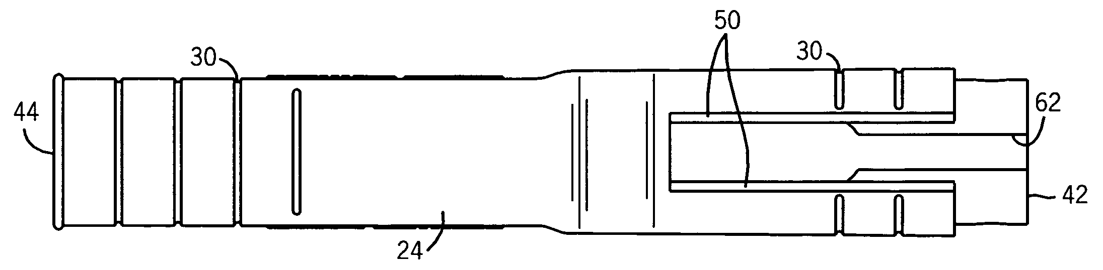
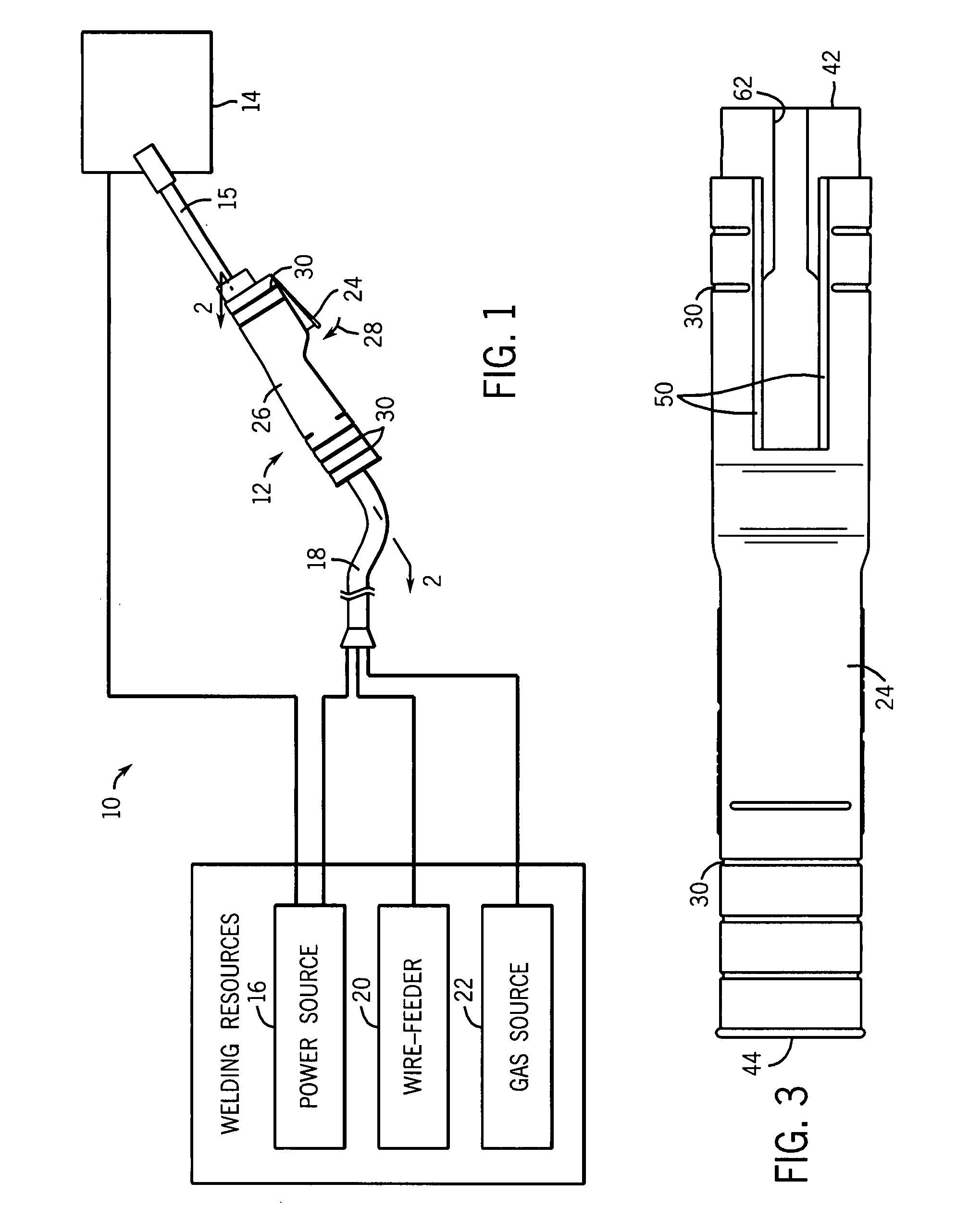
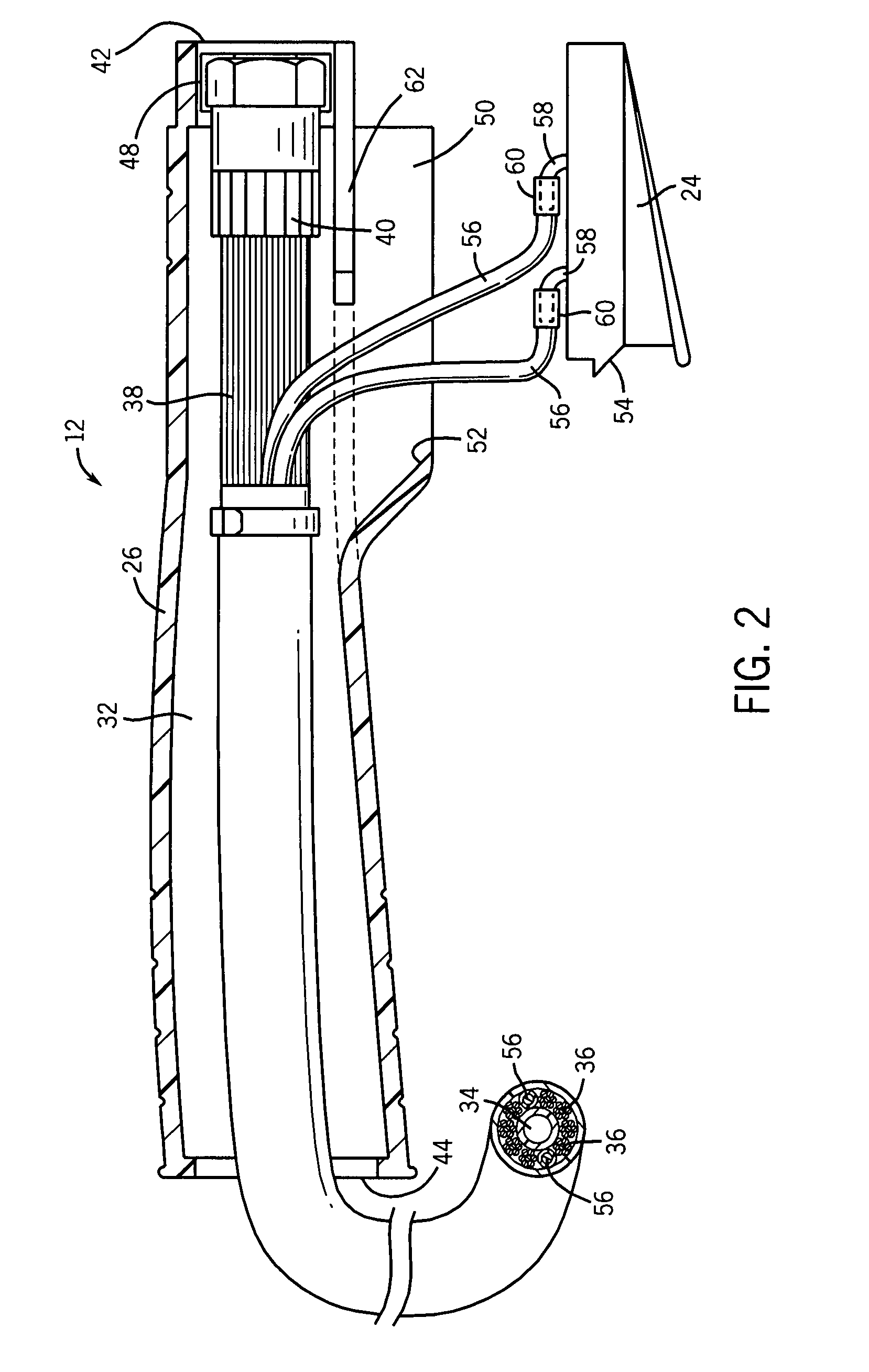
[0013]As discussed in detail below, embodiments of the present technique provide a handle with an unenclosed slot that facilitates coupling of insulated conductors extending from a welding cable disposed inside a handle to a trigger located outside of the handle. Advantageously, the unenclosed nature of the slot reduces the need for threading of the insulated conductors from the interior of the handle, which can be a labor-intensive process, for instance. FIG. 1 illustrates an exemplary gas shielded, wire-feed welding system 10 that incorporates such an unenclosed slot. Prior to continuing, however, it is worth noting that the following discussion merely relates to exemplary embodiments of the present technique. As such, the appended claims should not be viewed as limited to those embodiments described herein.

[0014]Returning to the exemplary welding system 10, it includes a welding torch 12 that defines the location of the welding operation with respect to a workpiece 14. Placement ...


PUM

PropertyMeasurementUnit
shapeaaaaaaaaaa
dielectricaaaaaaaaaa
widthsaaaaaaaaaa

Abstract

In accordance with one embodiment, the present technique relates to a welding torch handle that has an unenclosed slot extending from one end thereof. This unenclosed slot provides a mechanism through which insulated signal leads of a conductor can extend from the interior of the handle to connect with a trigger disposed outside the handle. As one advantage, the unenclosed nature of the slot facilitates this coupling without the need for threading of the leads, which can damage the leads.

Description

BACKGROUND[0001]The present technique relates generally to welding torches and, more particular, to a welding torch handle.[0002]A common metal welding technique employs the heat generated by electrical arcing to transition a workpiece to a molten state, to facilitate a welding process. One technique that employs this arcing principle is wire-feed welding. At its essence, wire-feed welding involves routing welding current from a power source into an electrode that is brought into close proximity with the workpiece. When close enough, current arcs from the electrode to the workpiece, completing a circuit and generating sufficient heat to weld the workpiece. Often, the electrode is consumed and becomes part of the weld itself.[0003]Furthermore, to prevent the ingress of impurities into the molten weld, a flow a shielding material is typically provided to the weld location. By way of example, inert shielding gas is routed from a gas source, through a welding cable and welding torch, an...

Claims


Application Information

Patent Timeline
Patent Type & Authority Applications(United States)
IPC IPC(8): B23K9/16
CPCB23K9/173B23K9/282B23K9/323B23K9/298B23K9/295
Inventor SERIO, PETER
Owner ILLINOIS TOOL WORKS INC
Why Eureka
Try Eureka