Power architecture and braking circuits for DC motor-propelled vehicle

a technology of braking circuit and braking circuit, which is applied in the direction of motor/generator/converter stopper, electric device, dynamo-electric converter control, etc., can solve the problems of difficult control of flat spots are a further costly high maintenance operation, and it is difficult to control the power drawn from the traction motor in braking mode, so as to prevent the development of flat spots on the locomotive wheels, reduce the downtime and maintenan

Inactive Publication Date: 2008-11-27
RAILPOWER LLC
View PDF3 Cites 29 Cited by
  • Summary
  • Abstract
  • Description
  • Claims
  • Application Information

AI Technical Summary

Benefits of technology

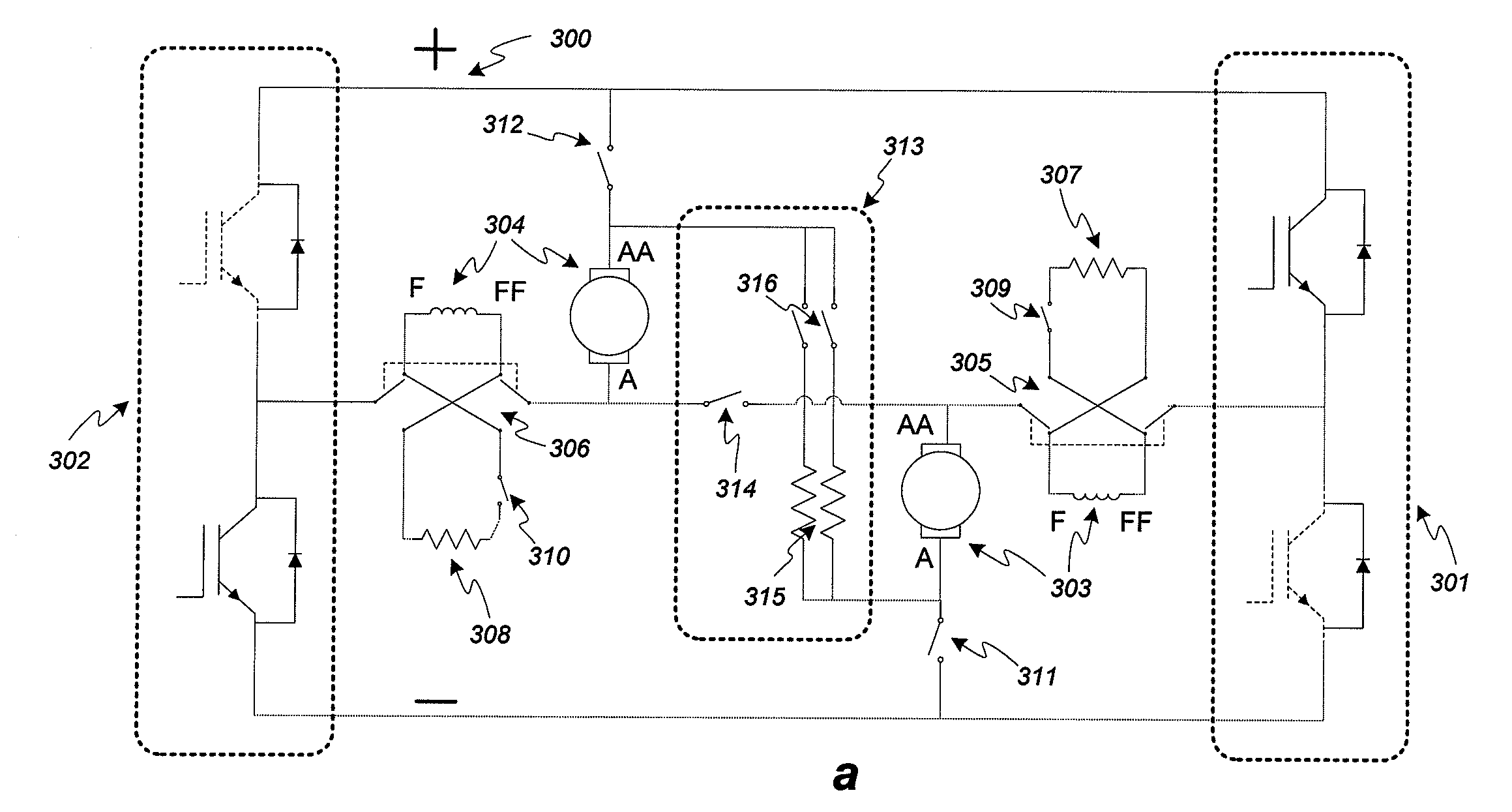
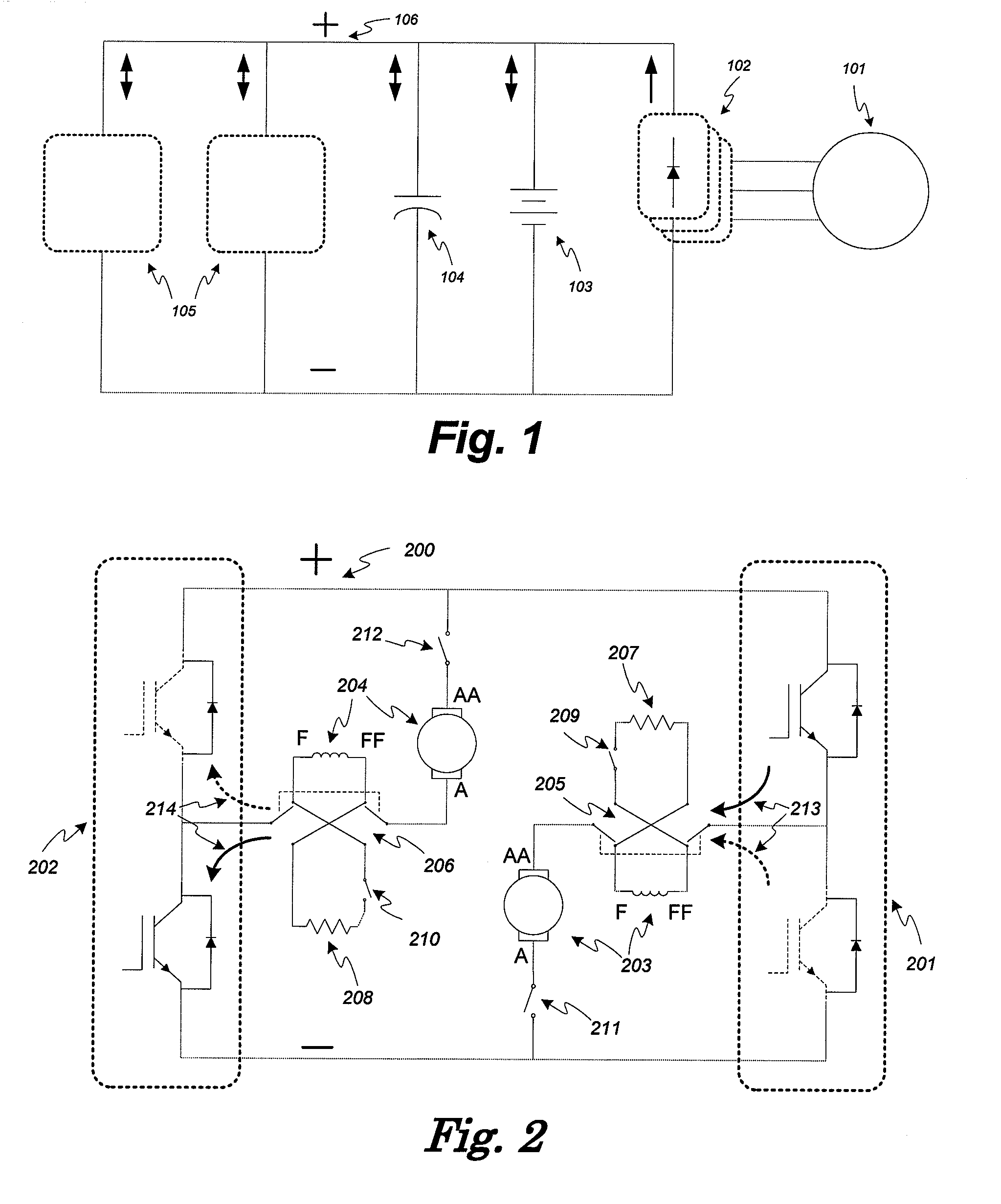
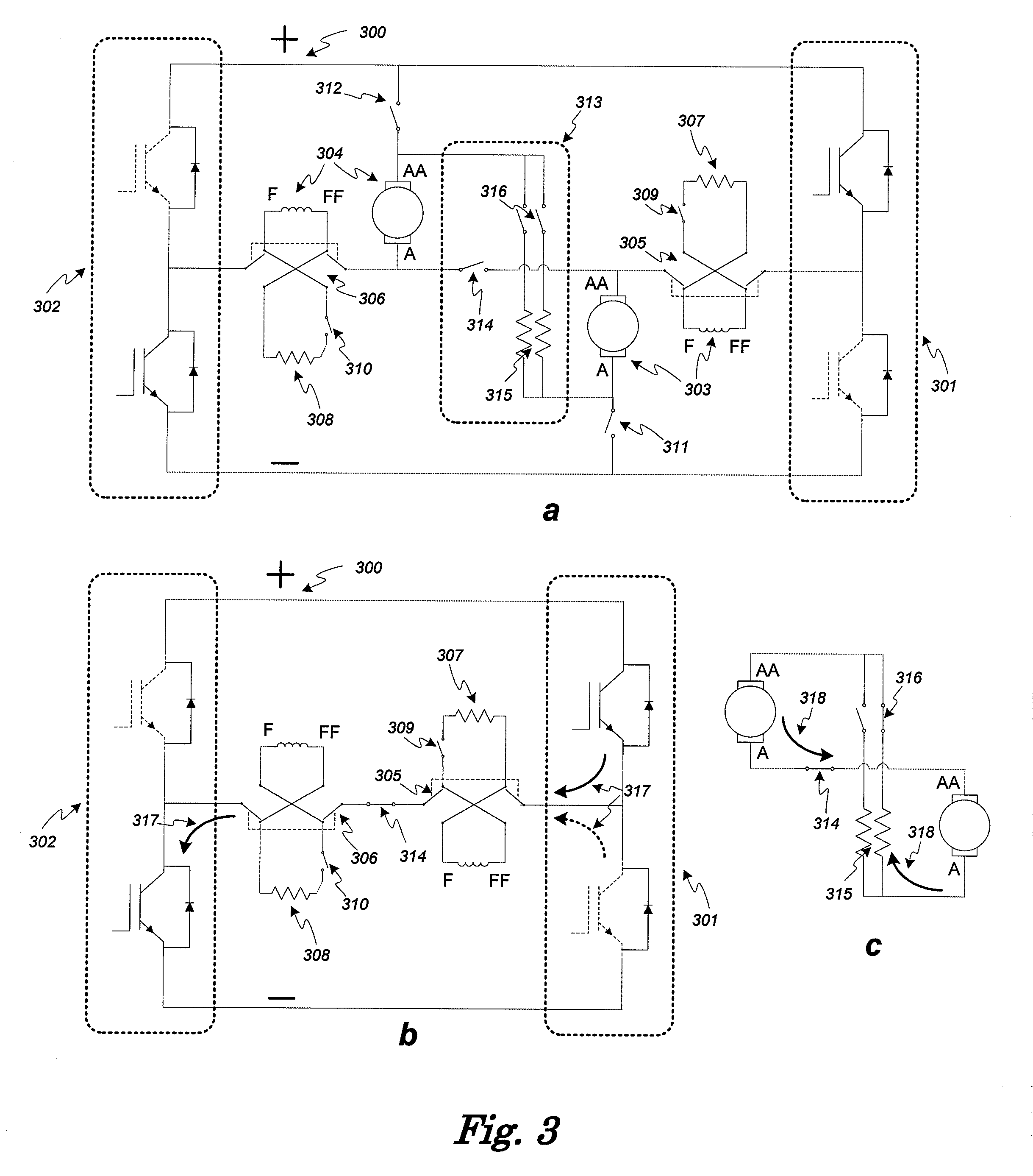
[0027]Variants of this second embodiment are presented as alternatives enabling common braking resistance sharing amongst several pairs of traction motor circuits. In another variant of the second invention, a dynamic braking circuit is disclosed that can control motor torque, even at zero speed, thus enabling fast traction reversal.
[0028]By utilizing the dynamic braking circuit configurations described above, the possibility of wheel skid such as can occur when mechanical brakes lock up can be effectively eliminated. This, in turn, prevents flat spots from developing on locomotive wheels. Thus, the various embodiments of the present invention have the advantage of substantially reducing locomotive downtime and maintenance which are significant problems, for example, in yard switching operations. For example, multiple locomotives have been used in yard switching operations involving long trains to minimize wheel skid occurrences and pneumatic brake maintenance when the only the locomotives' independent braking systems are used. This is a wasteful practice since the multiple locomotives can generate far more power, produce more emissions and consume far more fuel than required. When the dynamic braking methods of the present invention are used, the mechanical brakes of the vehicle need only be used in heavy braking or emergency braking situations. This practice will substantially eliminate occurrences of wheel skid most typically associated with pneumatic brake systems. Thus locomotive brake maintenance problems can be minimized while using only one locomotive with concomitant savings in fuel costs and reduction of emissions.

Problems solved by technology

In this configuration with both windings in series, it may be difficult to control the power drawn from the traction motors in braking mode.
Further, if the brake system locks up, it can cause wheel skid which can result in flat spots developing on the skidding wheels.
Flat spots are a further costly high maintenance operation usually requiring wheel replacement.

Method used


Image

  • Power architecture and braking circuits for DC motor-propelled vehicle
  • Power architecture and braking circuits for DC motor-propelled vehicle
  • Power architecture and braking circuits for DC motor-propelled vehicle

Examples


second embodiment

Improved “Soft” Extended Braking Circuit

[0082]The circuit of FIG. 5 is a preferred embodiment configuration for a regenerative and / or dynamic braking circuit. As shown in the figure, only the required components of the circuit are illustrated which consist mainly in 2 choppers (501, 502), a braking resistor grid 515, braking resistor selectors 516 and three reversers (505, 506&508) per pair of motors. However, it is possible to add any number of extra contactors or switches for isolation, protection and security without affecting the basic operation of the invention. As presented in FIG. 5, the circuit is in normal motoring mode.

[0083]FIG. 6 illustrates specifically the circuit in motoring mode where the current 611 in motor 603 series connected field and armature windings is controlled, as in previous circuits of FIGS. 1 and 2, by the chopper 601. Similarly, current 612 in motor 604 is controlled by chopper 602. Reverser switch 608 is configured so as to isolate the two motor circu...


PUM


Abstract

A dynamic braking circuit that can be operated with stability over both high and low speed regimes. This circuit has the advantage of using fewer components than previous circuits. In addition, when in braking mode, the armature and field currents tend to oppose each other across the main braking switch hence reducing electromechanical stresses when in high current regime. According to a second embodiment, a dynamic braking circuit implements a “soft” extended braking function with the capability of providing a smoother braking action at high braking effort at little extra cost resulting from the replacement of a contactor by a reverser. The main advantages of this preferred embodiment are that the current generated by the armatures during braking can be controlled independently from the excitation of the field windings at low speeds and that it enables simultaneous self supply, regeneration and dynamic braking.

Description

[0001]The present application claims priority of U.S. Provisional patent application No. 60 / 940,370 filed May 25, 2007, the contents of which are incorporated herein by reference.FIELD OF THE INVENTION[0002]The present invention relates generally to a method for configuring traction and dynamic braking circuits for a combination of several Series DC motors supplied by a DC bus, as can be found on locomotives, which are operable at low speeds and are adaptable to regenerative braking.BACKGROUND OF THE INVENTION[0003]Electrically propelled vehicles benefit from the advantage of being able to operate their traction motors in generator mode in order to produce braking energy that can be either dissipated in heat through a resistive load or recuperated in an electrical storage medium such as batteries. In both cases, there is a clear benefit in reduced maintenance of the otherwise standard mechanical friction brakes.[0004]The use of high power series DC traction motors driven by electron...

Claims


Application Information

Patent Timeline
Patent Type & Authority Applications(United States)
IPC IPC(8): H02P3/12
CPCB60L7/12B60L2200/26Y02T10/7258B60L2220/18Y02T10/72
Inventor ST-JACQUES, ALAINTARNOW, ANDREW C.DONNELLY, FRANK WEGNER
Owner RAILPOWER LLC
Why Eureka
Try Eureka