Illumination unit

a technology of a unit and a cavity is applied in the field of illumination units, which can solve the problems of corresponding volume of the assembly, however expensive, and achieve the effect of improving heat dissipation

Active Publication Date: 2008-11-27
OSRAM GMBH
View PDF10 Cites 29 Cited by
  • Summary
  • Abstract
  • Description
  • Claims
  • Application Information

AI Technical Summary

Benefits of technology

[0005]An object of the present invention is therefore to achieve improved heat dissipation as easily as possible for an illuminatio

Problems solved by technology

This is however costly and requires a

Method used


Image

  • Illumination unit
  • Illumination unit
  • Illumination unit

Examples


Embodiment Construction

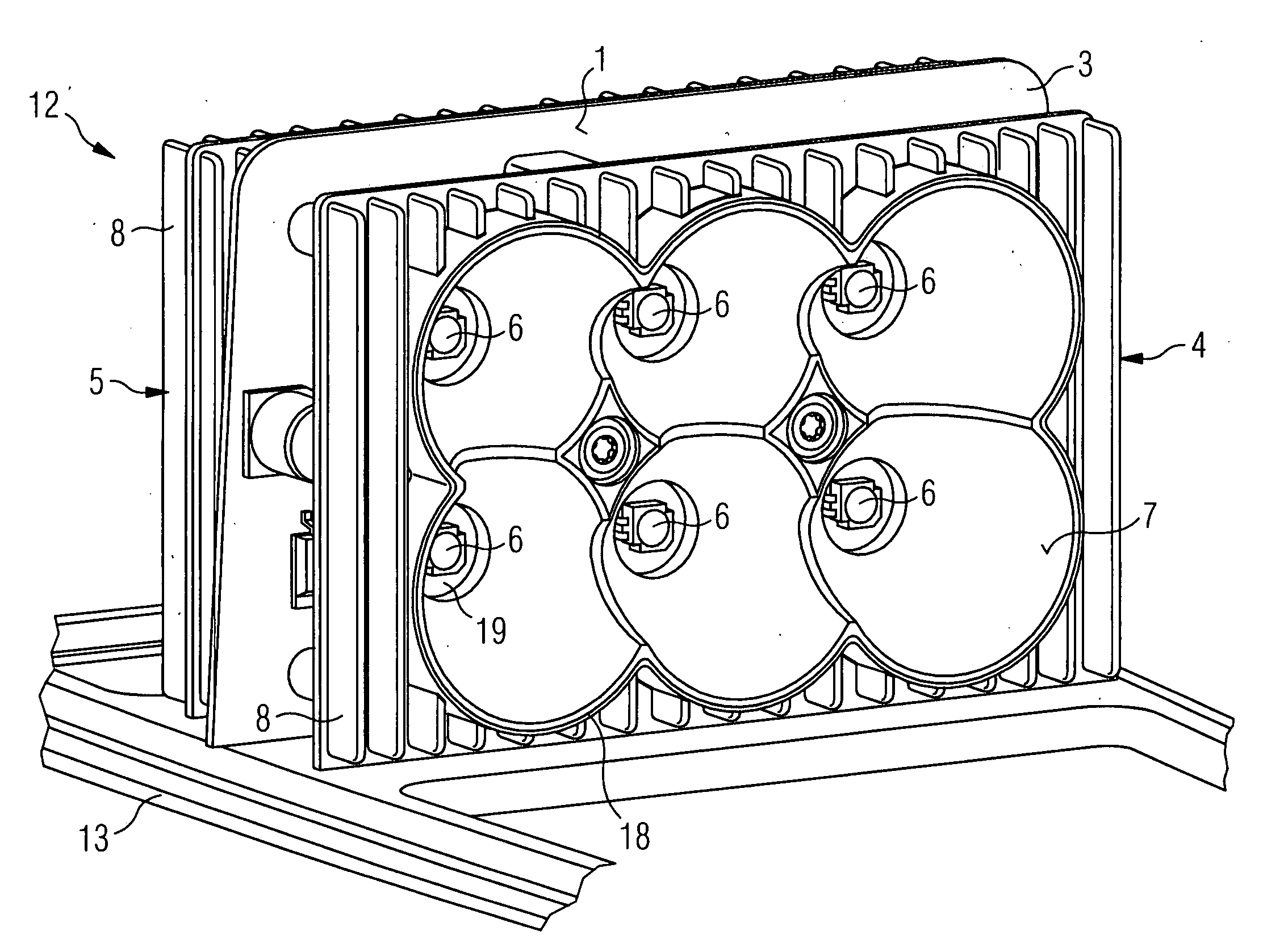
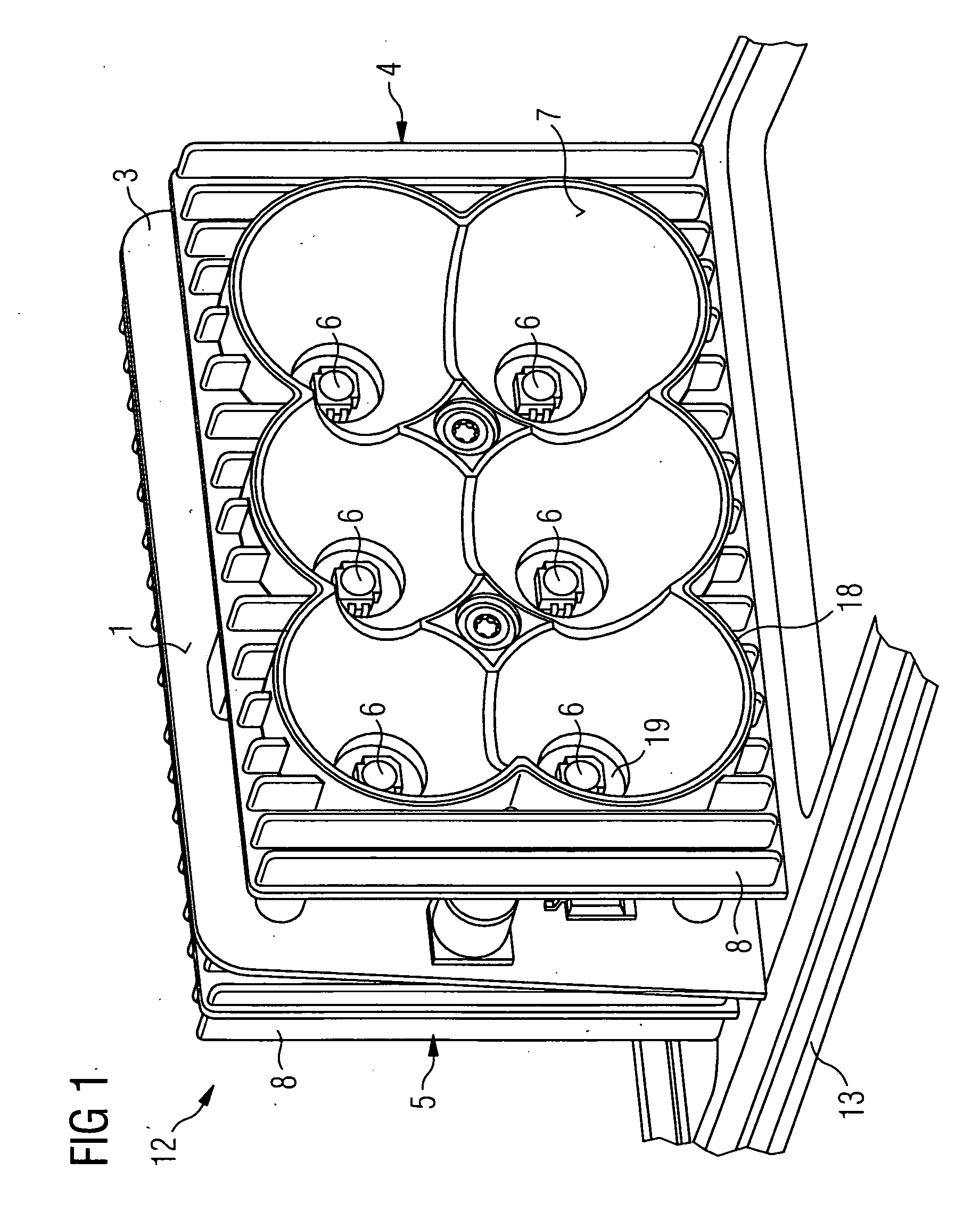
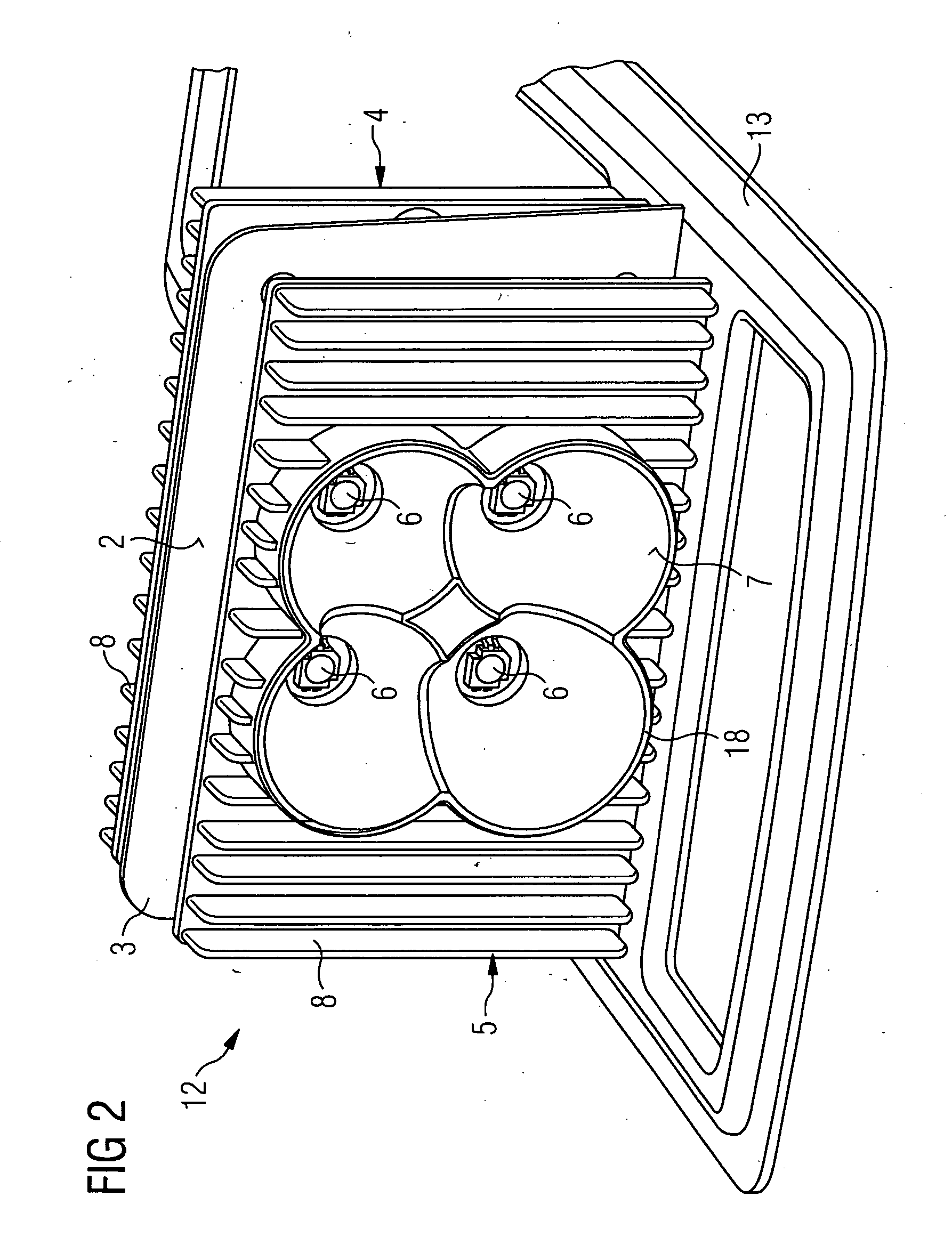
[0031]FIGS. 1 and 2 show an exemplary embodiment of the inventive illumination device in a spatial representation viewed from the front and from the rear. The illumination unit as a whole has the reference number 12. In the present example, it consists essentially of a printed circuit board 3, equipped on both sides with high-power light-emitting diodes 6 and held together in the form of a sandwich between two heat sinks 4,5 by means of fastening bolts 20. Each heat sink consists of cooling fins 8. These cooling fins 8 point in each case in the direction in which light is radiated from the reflectors 18 which are embodied on each heat sink 4 and 5. The heat sink 4 or 5 forms together with the respective reflector 18 a constructional unit which performs in each case the dual function of heat dissipation and guidance of light rays. The heat sinks 4 or 5 in this example are arranged as injection molded bodies made from metal and arranged on a baseplate 13.

[0032]As is best seen from the...


PUM


Abstract

There is described an illumination unit with a planar carrier part having a plurality of light-emitting semiconductor components, in particular high-power light-emitting diodes, arranged on both sides of a main surface. On each side of the carrier part a heat sink is provided in each case. Each of the semiconductor components is connected in an efficient heat-conducting manner to a heat sink provided on an opposite side of the carrier part by way of a heat conducting means that is fed through an opening in the carrier part. At least one reflector is embodied on each heat sink having a reflective surface which concentrates the emitted light from a semiconductor component which is arranged on the side of the carrier part facing this heat sink.

Description

CROSS REFERENCE TO RELATED APPLICATIONS[0001]This application claims priority of German application No. 10 2007 023 918.3 DE filed May 23, 2007, which is incorporated by reference herein in its entirety.FIELD OF INVENTION[0002]The invention relates to an illumination unit with a planar carrier part having a plurality of light-emitting semiconductor components, in particular high-power light-emitting diodes, arranged on each of the two sides and with a heat sink being provided on each side of said carrier part.BACKGROUND OF INVENTION[0003]It is known that in motor vehicles various illumination devices, such as flashing lights, are used in which light is emitted in both a forward and a backward direction. Nowadays, semiconductor components, in particular high-power light-emitting diodes (LEDs), are used as light-emitting components, as is known for example from DE 101 17 889 A1. The power consumption of these high-power LEDs is generally between 1 and 3 W or higher, which means that i...

Claims


Application Information

Patent Timeline
IPC IPC(8): H05K7/20F21V7/00F21V29/505
CPCF21S48/10F21V29/763F21S48/328F21V19/001F21V29/004F21W2101/12F21W2101/14F21Y2101/02H05K1/0206H05K3/0061H05K2201/10106F21S48/232Y10S362/80F21V29/505F21V29/71F21V29/75F21S48/215F21Y2115/10F21S43/14F21S43/37F21S45/47F21W2103/20F21V29/74F21W2103/00
Inventor HELLINGER, LEOPOLDNEUMANN, GERHARD
Owner OSRAM GMBH
Why Eureka
Try Eureka