Optical fiber, sealing method for optical fiber end face, connection structure of optical fiber, and optical connector

a technology of sealing method and end face, applied in the direction of optical waveguide light guide, optical light guide, instruments, etc., can solve the problems of increased connection loss, decreased long-term reliability, and problems such as problems, to achieve the effect of reducing the loss of optical fiber and increasing long-term reliability

Inactive Publication Date: 2008-11-27
HITACHI CABLE
View PDF7 Cites 8 Cited by
  • Summary
  • Abstract
  • Description
  • Claims
  • Application Information

AI Technical Summary

Benefits of technology

[0015]In view of the foregoing and other exemplary problems, drawbacks, and disadvantages of the conventional methods and structures, an exemplary feature of the present invention is to provide an optical fiber, a sealing method for the optical fiber, a connection structure of the optical fiber, and an optical connector, which have a high reliability.
[0045]According to the present invention, a reliability of the optical fiber, the sealing method for the optical fiber, the connection structure of the optical fiber, and the optical connector can be improved.

Problems solved by technology

However, when the optical fibers such as a holey fiber having holes are connected by the above connecting method, problems may occur.
Thus, light will be coupled to the core of the holes, and a connection loss will be increased.
Thus, when repeating an attachment and a removal of the connector, the grinding wastes entering into the holes may be present at the optical fiber end face, a crack or a void may occur, and a long-term reliability may decrease.
However, according to the conventional sealing method for the optical fiber end face, although the holes of the optical fiber end face are sealed by hardening a hardening resin injected in the holes by an ultraviolet irradiation or a heat, where the hardening resin easily permeates a moisture, the moisture permeating through a sealing portion under a high humidity condition produces a condensation inside of the holes, and the transmission loss is extremely increased.
Further, according to the conventional connecting method, where an adhesive strength between the hardening resin and a glass is small, an air gap or a separation between the resin and an inner wall of the holes will occur easily due to a volume contraction of the hardening resin during hardening.
Thereby, in a butt connection by the mechanical splice, the refractive index matching agent enters into the holes from a gap (e.g., separation), and the connection loss is increased.
Still further, according to the conventional optical connector, a reliability is decreased due to entry of a grind agent or a grinding waste into the gap.
Additionally, if the hardening resin is too soft, a resin surface thereof may sag more than a glass surface in grinding, then the grinding waste etc. may settle in the sagging area, and a connection error may be caused thereby.

Method used


Image

  • Optical fiber, sealing method for optical fiber end face, connection structure of optical fiber, and optical connector
  • Optical fiber, sealing method for optical fiber end face, connection structure of optical fiber, and optical connector
  • Optical fiber, sealing method for optical fiber end face, connection structure of optical fiber, and optical connector

Examples


first exemplary embodiment

Configuration of Optical Fiber

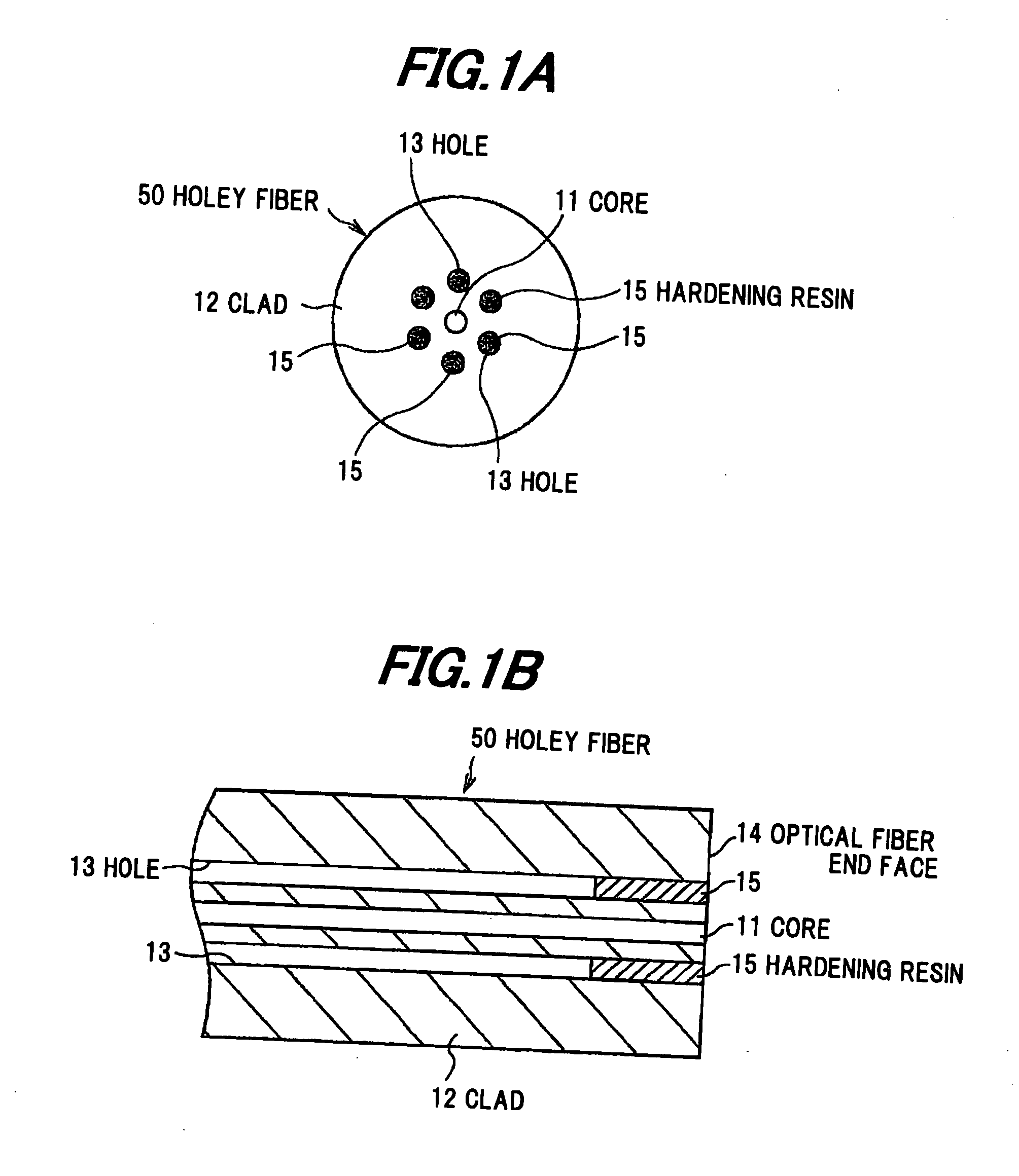
[0058]FIGS. 1A and 1B show an optical fiber in a first exemplary embodiment according to the present invention, in which FIG. 1A is a front view and FIG. 1B is a side sectional view of the optical fiber.

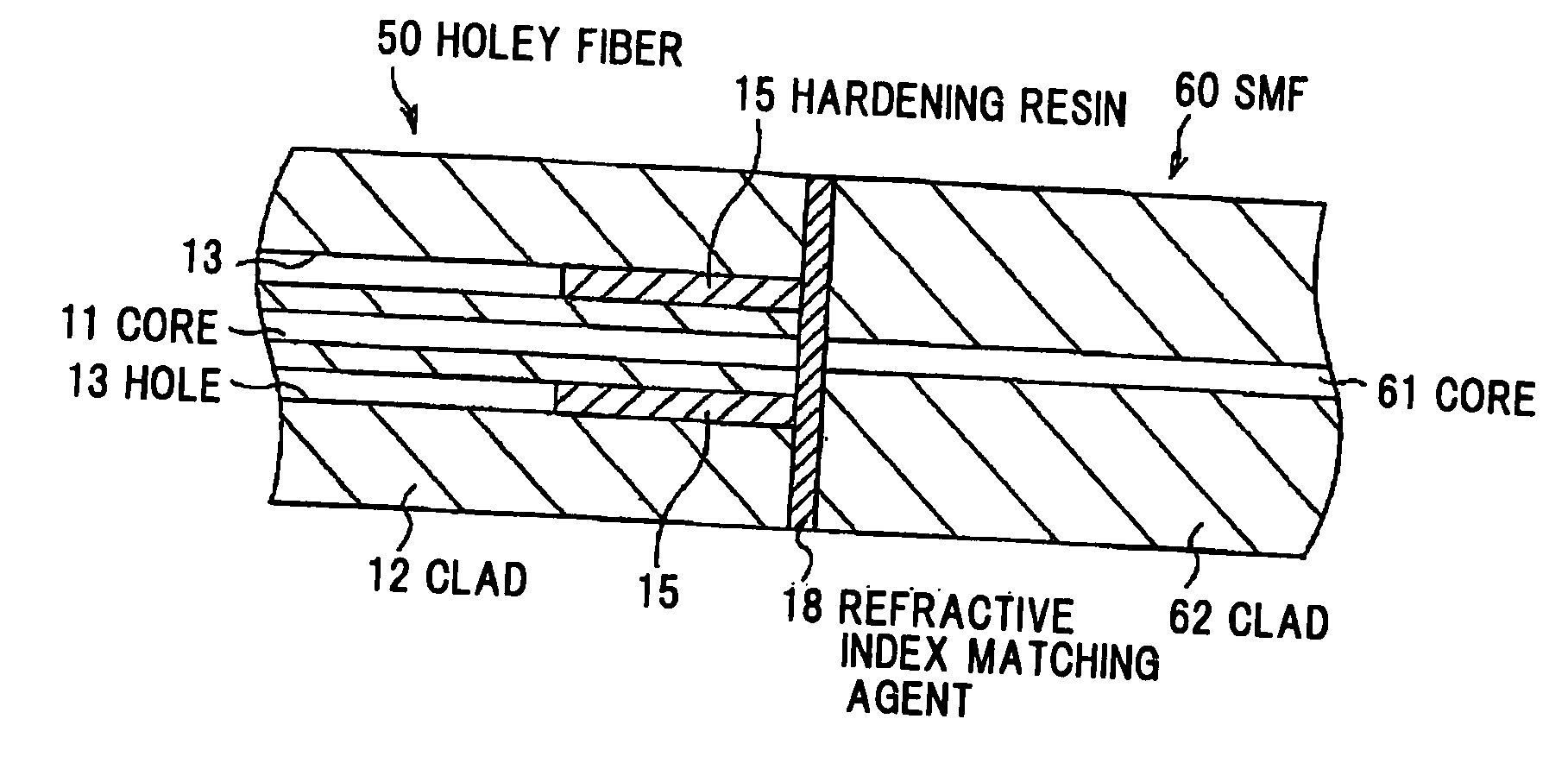
[0059]A holey fiber 50 includes a core 11 formed so as to be solid, a clad 12 formed around the core 11, and a plurality of holes 13 which are formed around the core 11 and have a refractive index of about 1. The holey fiber 50 further includes a hardening resin 15 filled in the holes 13 of an optical fiber end face 14. In FIGS. 1A and 1B, an end face of the core 11 is formed so as to constitute the same end face of the holey fiber 50.

[0060]The hardening resin 15 may be a resin having a moisture permeability, after hardening, equal to or less than 0.5 g / cm2·24 hr. If the moisture permeability of the hardening resin 15 is greater than 0.5 g / cm2·24 hr, then a condensation easily occurs in the holes under a high humidity condition, and the transmission loss...

examples

[0072]Next, examples of the present invention are described.

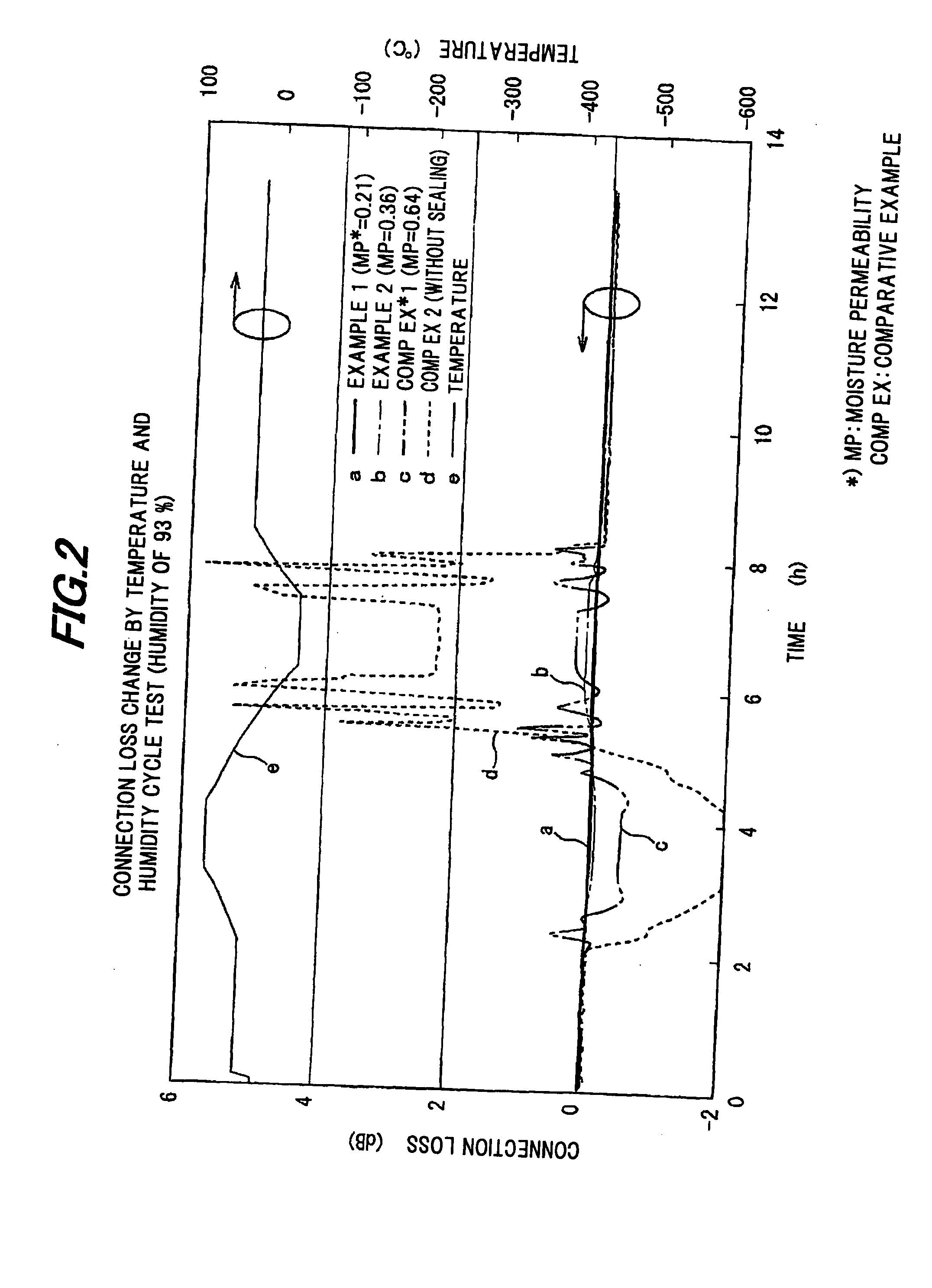
[0073]FIG. 2 is a view showing a connection loss characteristic of the optical fiber in the first exemplary embodiment.

[0074]This represents a change of the connection loss, where an SC (Single Coupling) connector is attached to the end face of the holey fiber 50 in which the holes 13 are sealed by the hardening resin 15, an optical fiber in which a universal SC connector is attached to a normal single mode fiber (SMF) is connected to the holey fiber 50, a connecting part thereof is entered into a constant-temperature bath, and a temperature and humidity cycle test (−40 to +70° C., 93% RH) is performed.

[0075]In FIG. 2, Example 1 is 0.21 g / cm2·24 hr in moisture permeability, Example 2 is 0.36 g / cm2·24 hr in moisture permeability, and Comparative Example 1 is 0.64 g / cm2·24 hr in moisture permeability.

[0076]Clearly, as shown in FIG. 2, a connection loss change of Comparative Example 1 having a high moisture permeability and Co...

second exemplary embodiment

[0100]FIG. 7 is a sectional view showing an optical connector in a second exemplary embodiment according to the present invention. This optical connector 100 includes a ferrule 21 having a hollow fixing portion 22 for fixing the holey fiber 50 and a flange 26, and a fiber holding portion 23 which holds a fiber core wire 17 of the holey fiber 50 and is connected to the ferrule 21.

[0101]The hardening resin 15 is filled in the holes 13 of the holey fiber 50. Thereby, it is prevented that the grinding waste occurring when the optical fiber end face 14 and a ferrule end face 24 are grinded (e.g., polished), enters into the holes 13, and that a crack or a void occurs in the optical fiber end face 14 due to the grinding waste when the optical connector 100 is attached or removed.

[0102]FIG. 8 is a sectional view showing a step of filling a thermosetting resin into a ferrule.

[0103]FIG. 9 is a sectional view showing a step of fixing a holey fiber to the ferrule.

[0104]Hereinafter, referring to...


PUM

PropertyMeasurementUnit
viscosityaaaaaaaaaa
refractive indexaaaaaaaaaa
humidityaaaaaaaaaa

Abstract

An optical fiber includes a core, a clad formed around the core, a plurality of holes being formed in the clad, and a hardening resin having a moisture permeability equal to or less than 0.5 g / cm2·24 hr, in which the hardening resin is filled in a vicinity of an end face of the holes.

Description

[0001]The present application is based on Japanese Patent Application No. 2007-134772 filed on May 21, 2007, the entire contents of which are incorporated herein by reference.BACKGROUND OF THE INVENTION[0002]1. Field of the Invention[0003]This invention relates to an optical fiber which includes plural holes extending in a longitudinal direction thereof, a sealing method for the optical fiber, a connection structure of the optical fiber, and an optical connector using the optical fiber.[0004]2. Description of the Related Art[0005]To increase speed of an optical communication network and an optical signal processing, an optical fiber having a larger capacity is necessary. As means for achieving such an increased speed, a photonic crystal fiber (PCF) in which multiple holes stretching in a longitudinal direction are formed, has been considered.[0006]An example of a total reflection PCF is a holey fiber (HF), in which a plurality of holes are formed in a clad surrounding a Ge-doped cor...

Claims


Application Information

Patent Timeline
Patent Type & Authority Applications(United States)
IPC IPC(8): G02B6/032G02B6/26G02B6/36
CPCG02B6/02366G02B6/02385G02B6/25
Inventor KATO, YOSHIHISASUZUKI, KANAKOKUROSAWA, YOSHINORIOHSONO, KAZUMASA
Owner HITACHI CABLE
Why Eureka
Try Eureka