

Membrane electrode assembly including porous catalyst layer and method of manufacturing the same
a catalyst layer and membrane electrode technology, applied in the manufacture of final products, cell components, electrochemical generators, etc., can solve the problems of reduced oxygen adsorption capacity, reduced overall porosity, and difficult removal of water in the catalyst layer, so as to achieve effective oxygen transfer and water removal, the effect of improving efficiency
- Summary
- Abstract
- Description
- Claims
- Application Information
AI Technical Summary
Benefits of technology
Problems solved by technology
Method used
Image

Examples
example 1
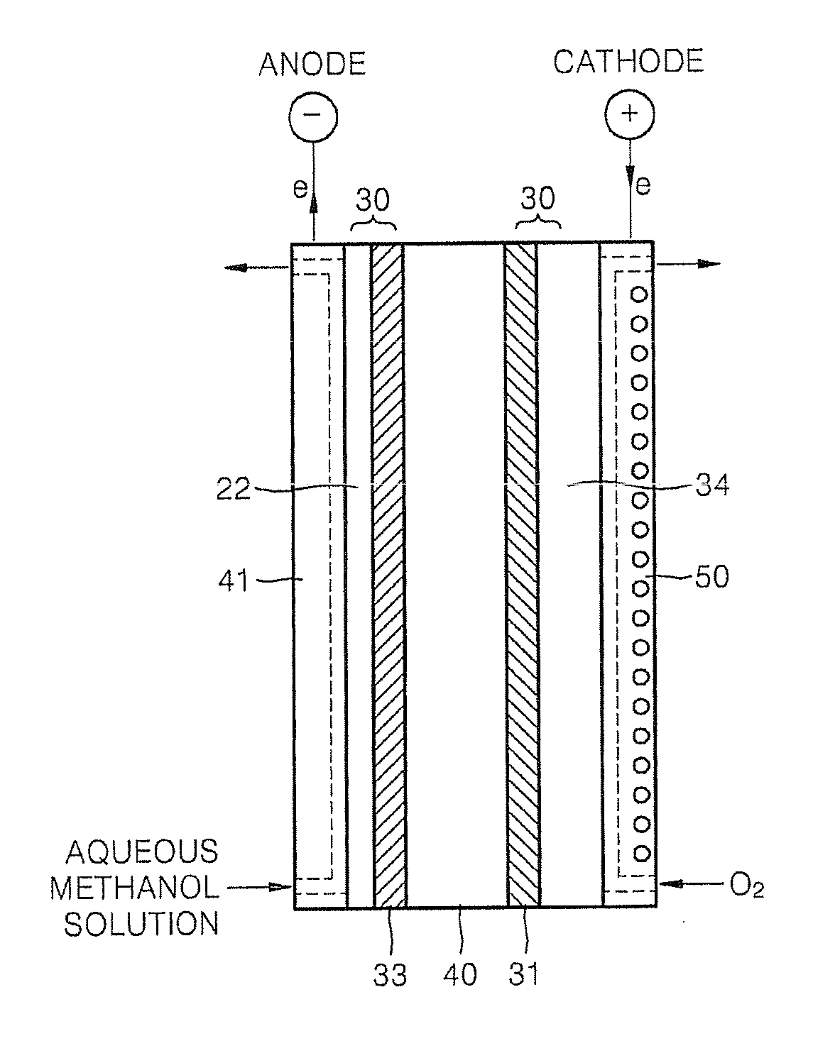
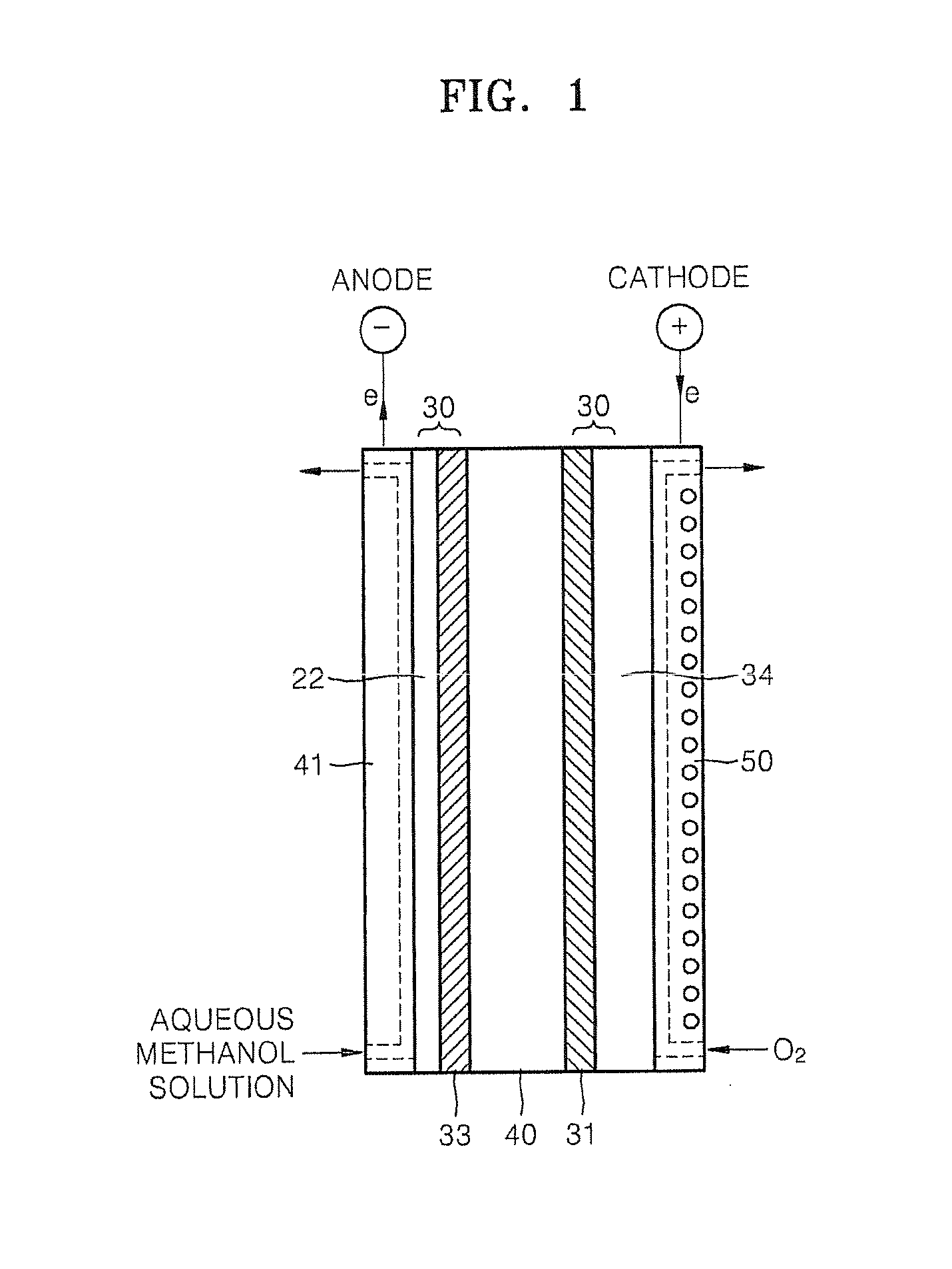
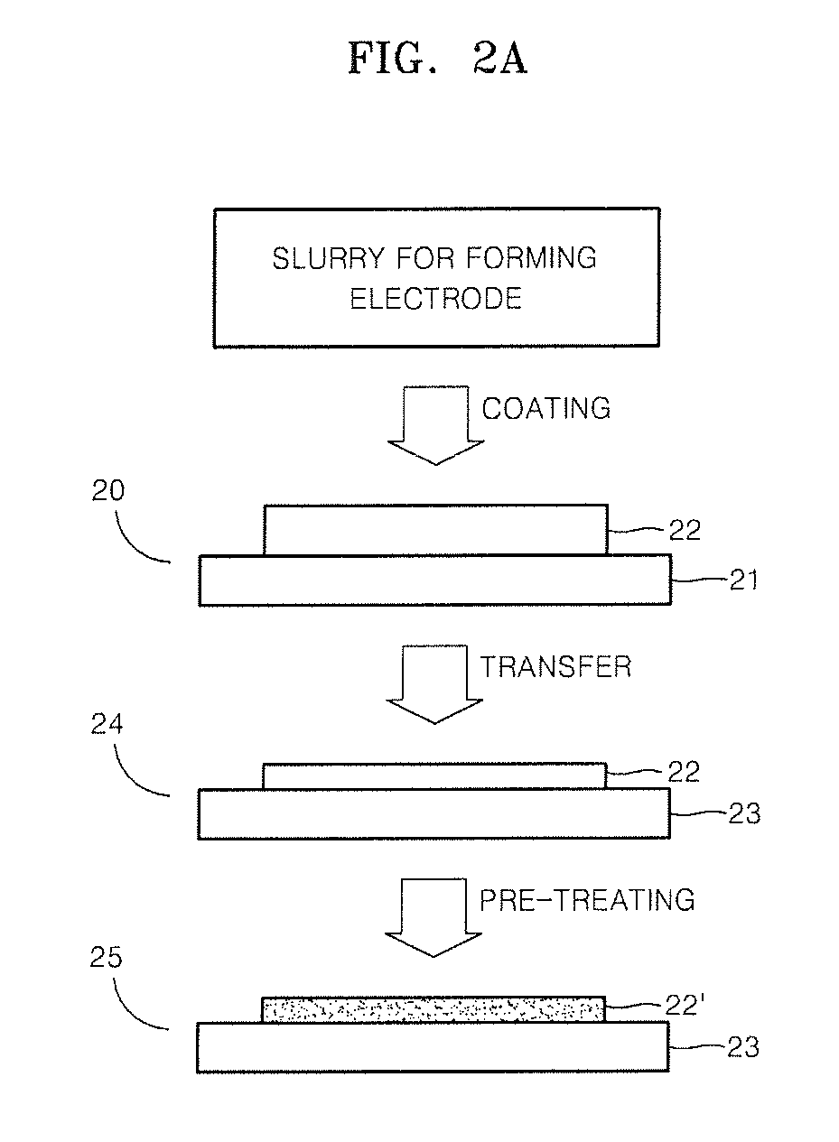
Using a Decal Transfer Method to Transfer a Catalyst Layer to an Electrolyte Membrane
[0065]0.4 g MgSO4 (20 parts by weight based on 100 parts by weight of a catalyst) and 1 g of water were added to a 20 ml reactor to completely dissolve the MgSO4, and then 2 g of Pt-black was added thereto. 1.25 g of 20 wt % NAFION® solution and 3 g of ethylene glycol (EG) were added to the reactor, and mixed using a high-speed mixer (from Thinky Corp.) for 3 minutes to prepare a cathode catalyst layer slurry. This mixing was performed three times to obtain uniform state of the cathode catalyst layer slurry.
[0066]Polytetrafluoroethylene (PTFE) film was used as a support membrane for a transfer film and was placed on bar-coater equipment on a flat glass plate, and then a predetermined region on the PTFE film was covered with polyethylene film having a thickness of 110 μm as a mask for patterning the cathode catalyst layer. The cathode catalyst layer slurry prepared above was poured on the resultant o...
example 2
Using a Decal Transfer Method to Transfer a Catalyst Layer to an Electrolyte Membrane
[0071]An MEA was prepared in the same manner as in Example 1 except that 0.3 g of MgSO4 (15 parts by weight based on 100 parts by weight of the catalyst) and 1 g water were added to completely dissolve MgSO4.
example 3
Using a Direct Coating Method to Directly Coat a Catalyst Layer on an Electrolyte Membrane
[0072]After preparing a cathode catalyst layer slurry identical to that of Example 1, a NAFION®-115 film (E. I. du Pont de Nemours and Company) was placed on a vacuum plate of a bar-coater equipment having a vacuum device, and then a predetermined region on the membrane was covered with polyethylene film having a thickness of 110 μm as a mask to pattern a cathode catalyst layer.
[0073]The cathode catalyst layer slurry prepared above was poured on the resultant obtained above in two steps, and then the bar-coater was slowly moved to prepare a uniform cathode catalyst layer on the electrolyte membrane on which the mask was covered. The prepared resultant was dried in a vacuum oven at 120° C. for 24 hours to directly coat the cathode catalyst layer on the electrolyte membrane.
[0074]After the coating of the cathode catalyst layer, an anode catalyst layer slurry to form an anode identical to that of ...
PUM
| Property | Measurement | Unit |
|---|---|---|
| porosity | aaaaa | aaaaa |
| pore diameter | aaaaa | aaaaa |
| specific surface area | aaaaa | aaaaa |
Abstract
Description
Claims
Application Information