Radiation Applicator and Method of Radiating Tissue

a tissue and radiation applicator technology, applied in the field of medical technology, can solve the problems of not having the heightened physical rigidity of known radiation applicator systems, not optimally mechanically configured for insertion into human skin, and difficult operation of liver cancer, so as to facilitate tissue insertion and provide strength and stiffness to the applicator.

Inactive Publication Date: 2008-11-27
MICROSULIS HOUSE
View PDF10 Cites 28 Cited by
  • Summary
  • Abstract
  • Description
  • Claims
  • Application Information

AI Technical Summary

Benefits of technology

[0017]In operation, microwave energy from a source is applied to the coaxial cable, and is conveyed to the tip. The portion of the inner conductor that extends beyond the end of the ferrule forms one arm of the dipole, and emits microwave radiation. In addition, the microwave energy flowing along the inner conductor of the coaxial cable and in the aperture of the ferrule induces a current to flow along the outer surface of the sleeve of the ferrule that is surrounded by the tip. This, in turn, causes microwave radiation to be emitted from the sleeve of the ferrule, which operates as the second arm of the dipole. In this way, microwave energy is emitted along a substantial length of the applicator, rather than being focused solely from the tip. By distributing the emission of microwave radiation along a length of the applicator, higher power levels may be employed.
[0019]The closed end of the tip is preferably formed into a blade or point so that the Microwave applicator may be inserted directly into the tissue being treated. The tip, ferrule, and rigid sleeve, moreover, provide strength and stiffness to the applicator, thereby facilitating its insertion into tissue.

Problems solved by technology

According to the method, there can be performed an operation on liver cancer, which has been conventionally regarded as very difficult.
However, a drawback with the existing techniques include the fact that they are not optimally mechanically configured for insertion into, and perforation of, the human skin, for delivery to a zone of soft tissue to be treated.
Typically, known radiation applicator systems do not have the heightened physical rigidity that is desirable when employing such techniques.
In addition, some radiation applicators made available heretofore do not have radiation emitting elements for creating a microwave field pattern optimized for the treatment of soft tissue tumors.
Also, given the power levels employed in some applicators and treatments, there can be problems of unwanted burning of non-target, healthy tissue due to the very high temperatures reached by the applicator or the components attached thereto.
Further, although small diameter applicators are known, and liquid cooling techniques have been used, there has been difficulty in designing a small diameter device with sufficient cooling in applications employing power levels required to deal with soft tissue tumors.

Method used


Image

  • Radiation Applicator and Method of Radiating Tissue
  • Radiation Applicator and Method of Radiating Tissue
  • Radiation Applicator and Method of Radiating Tissue

Examples


Embodiment Construction

[0036]In the following description, like references are used to denote like elements, and where dimensions are given, they are in millimeters (mm). Further, it will be appreciated by persons skilled in the art that the electronic systems employed, in accordance with the present invention, to generate, deliver and control the application of radiation to parts of the human body may be as described in the art heretofore. In particular, such systems as are described in commonly owned published international patent applications W095 / 04385, W099 / 56642 and WOOO / 49957 may be employed (except with the modifications described hereinafter). Full details of these systems have been omitted from the following for the sake of brevity.

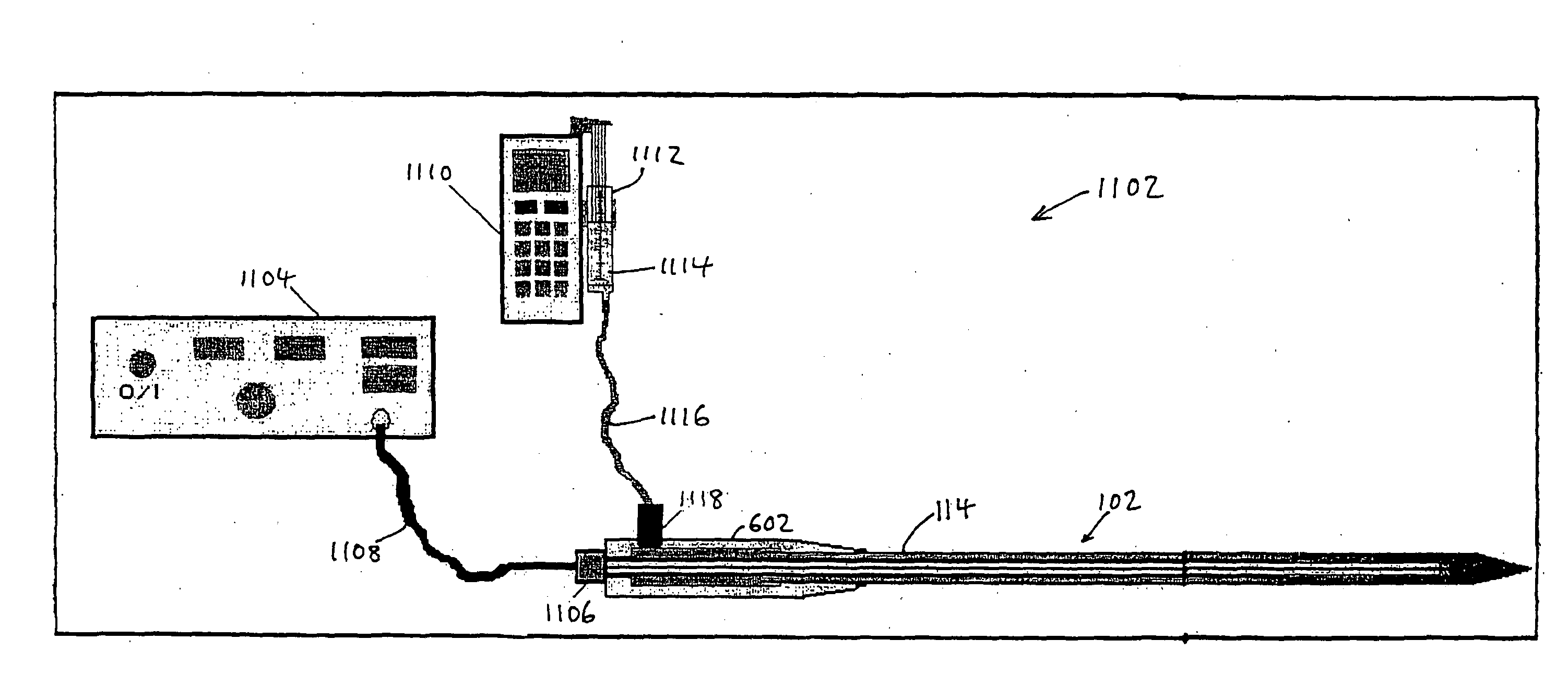
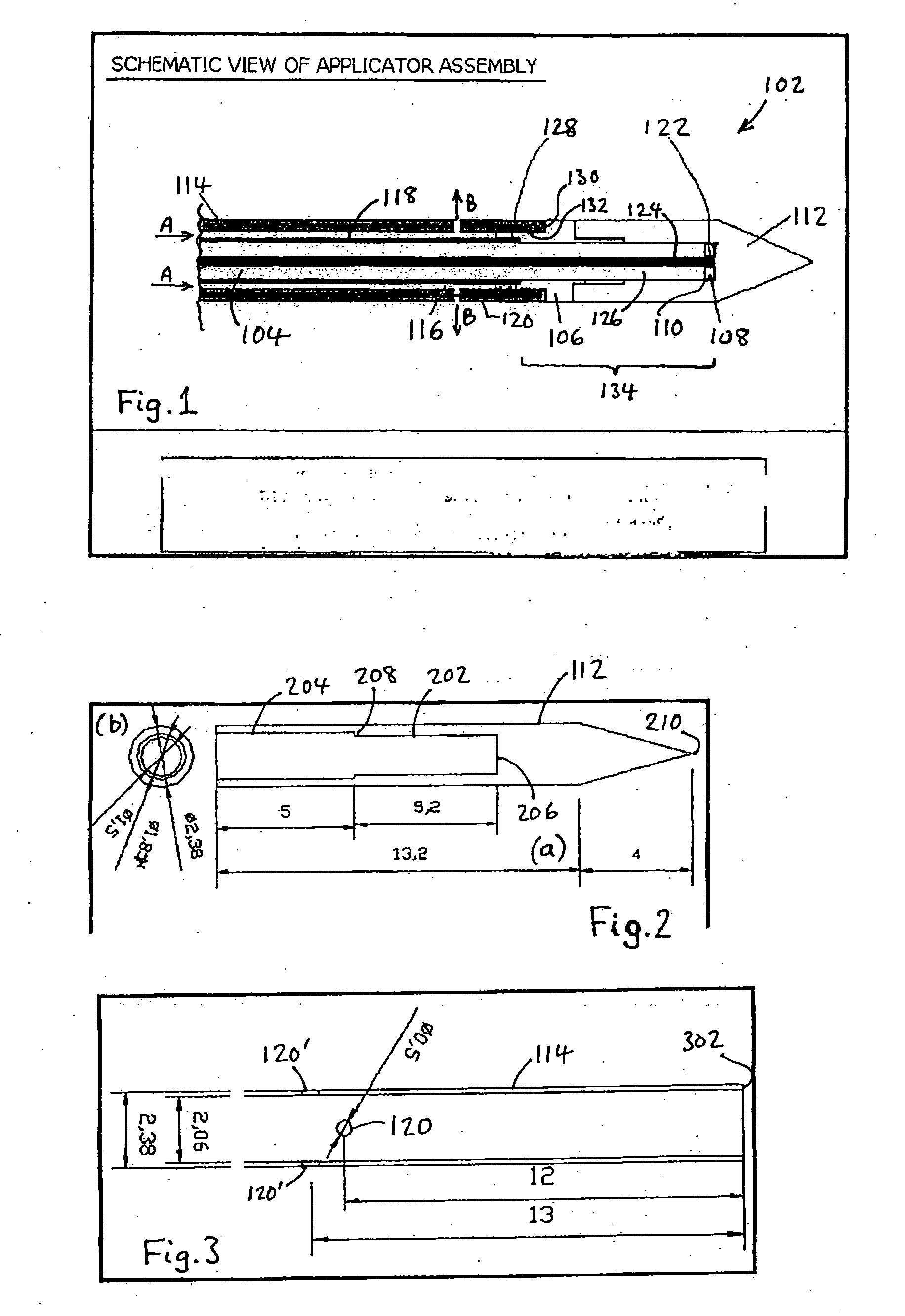
[0037]FIG. 1 is a schematic, partial cross-sectional view of a radiation applicator in accordance with one embodiment of the invention. The radiation applicator, generally designated 102, includes a distal end portion of a coaxial cable 104 that is used to couple to a...


PUM


Abstract

A dipole microwave applicator emits microwave radiation into tissue to be treated. The applicator is formed from a thin coax cable having an inner conductor surrounded by an insulator, which is surrounded by an outer conductor. A portion of the inner conductor extends beyond the insulator and the outer conductor. A ferrule at the end of the outer conductor has a step and a sleeve that surrounds a portion of the extended inner conductor. A tuning washer is attached to the end of the extended inner conductor. A dielectric tip encloses the tuning washer, the extended inner conductor, and the sleeve of the ferrule. The sleeve of the ferrule and the extended inner conductor operate as the two arms of the dipole microwave antenna. The tuning washer faces the step in the ferrule, and is sized and shaped to cooperate with the step in balancing and tuning the applicator.

Description

CROSS-REFERENCE TO RELATED APPLICATION[0001]The present application is related to commonly owned copending International patent application no. WO 2006 / 002943, concerning a Radiation Applicator and Method of Radiating Tissue and which is hereby incorporated by reference in its entirety.BACKGROUND OF THE INVENTION[0002]1. Field of the Invention[0003]The present invention relates generally to medical technology, and more specifically to microwave radiation applicators and methods of thermal ablative treatment of tissue using radiated microwaves.[0004]2. Background Information[0005]Thermal ablative therapies may be defined as techniques that intentionally decrease body tissue temperature (hypothermia) or intentionally increase body tissue temperature (hyperthermia) to temperatures required for cytotoxic effect, or to other therapeutic temperatures depending on the particular treatment. Microwave thermal ablation relies on the fact that microwaves form part of the electromagnetic spectr...

Claims


Application Information

Patent Timeline
Patent Type & Authority Applications(United States)
IPC IPC(8): A61B18/18
CPCA61B18/18A61B18/1815A61B2018/00029A61B2018/00577A61N5/045A61B18/04A61N5/00A61B2018/00023A61B2018/00077A61B2018/00083A61B2018/00178A61B2018/1838A61B2018/1869A61B2018/1892G06T7/30
Inventor CRONIN, NIGEL
Owner MICROSULIS HOUSE
Why Eureka
Try Eureka