Implantable Cardiac Stimulator , System, Device and Method for Monitoring Cardiac Synchrony

a cardiac synchrony and implantable technology, applied in the field of implantable cardiac synchrony monitoring devices, can solve the problems of not being suffer from compromised pumping performance, and not necessarily be able to meet the needs of patients, so as to improve the cardiac synchrony of the heart cycle, maintain or improve the cardiac synchrony, the effect of improving the cardiac synchrony

Active Publication Date: 2008-11-27
ST JUDE MEDICAL
View PDF14 Cites 13 Cited by
  • Summary
  • Abstract
  • Description
  • Claims
  • Application Information

AI Technical Summary

Benefits of technology

[0017]As stated above, a cardiac asynchrony result in a compromised pumping performance of the heart. Thus, one effect of maintaining or even improving the cardiac synchrony of the heart cycle, in particular during the systolic phase, is that the cardiac output may be maintained at a desired level, or even improved. Usually, an improvement in the cardiac output of a patient, i.e. the volume of blood ejected by the heart per minute, results in an improvement in the overall wellbeing of the patient.
[0018]Furthermore, it should in this context also be noted that the synchronization of myocardial relaxation during the diastolic phase of the heart cycle is beneficial for maintaining coronary flow at a desire...

Problems solved by technology

If these conduction pathways do not function properly, a slight or severe delay in the propagation of electrical pulses may arise, causing asynchronous contraction of the ventricles which would greatly diminish the pumping efficiency of the heart.
Patients who exhibit pathology of these conduction pathways, such as patients with bundle branch blocks, etc., can thus suffer compromised pumping performance.
However, even though ventricular and atrial ...

Method used


Image

  • Implantable Cardiac Stimulator , System, Device and Method for Monitoring Cardiac Synchrony
  • Implantable Cardiac Stimulator , System, Device and Method for Monitoring Cardiac Synchrony
  • Implantable Cardiac Stimulator , System, Device and Method for Monitoring Cardiac Synchrony

Examples


Embodiment Construction

[0057]The following is a description of exemplifying embodiments in accordance with the present invention. This description is not to be taken in a limiting sense, but is made merely for the purpose of describing the general principles of the invention. Thus, although particular types of heart stimulators will be described, such as biventricular pacemakers with or without atrial sensing and / or stimulation, the invention is also applicable to other types of cardiac stimulators, such as univentricular or dual chamber pacemakers, implantable cardioverter defibrillators (ICD's), etc.

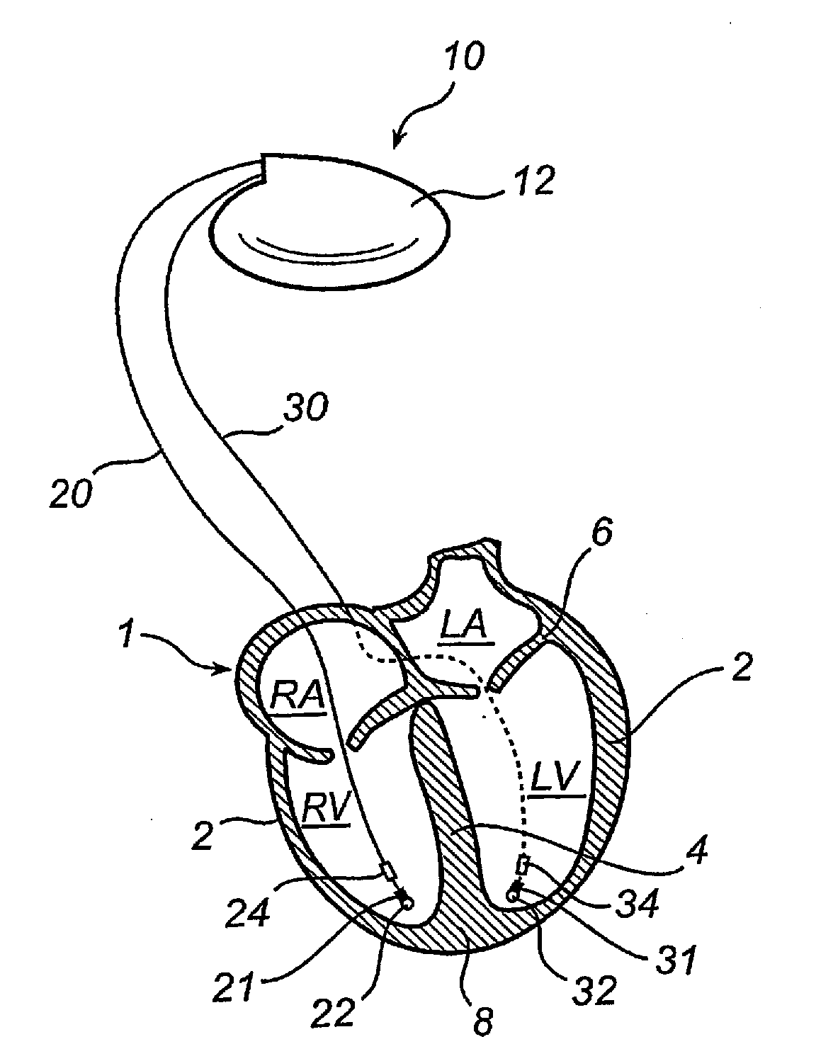
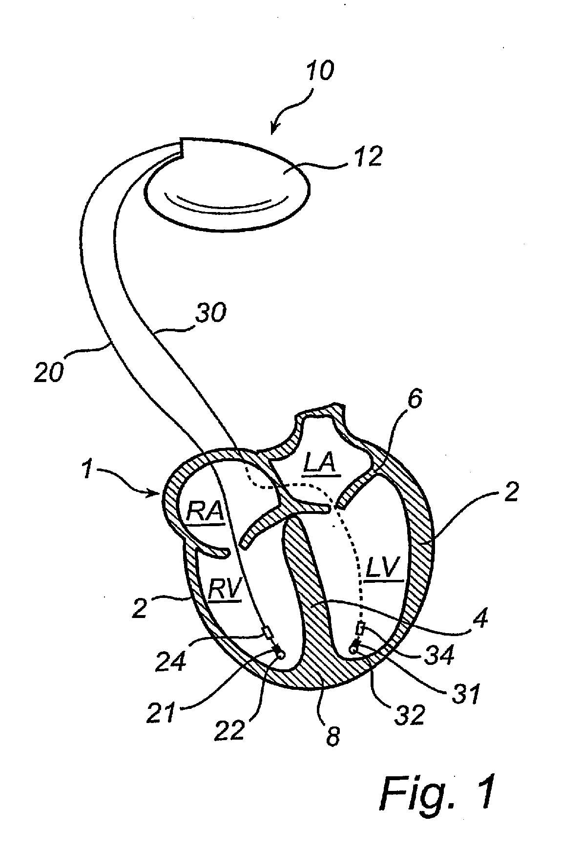
[0058]With reference first to FIG. 1, there is shown a stimulation device 10 in electrical communication with a patient's heart 1 via two leads 20 and 30 suitable for delivering multi-chamber stimulation (and possible shock therapy). The heart illustrated portions of the heart 1 include the right atrium RA, the right ventricle RV, the left atrium LA, the left ventricle LV, cardiac walls 2, the ventricular se...


PUM


Abstract

In a system and method for monitoring cardiac synchrony in a human heart, a first sensor is positioned at a first cardiac wall location of a heart that is subject to movements related to longitudinal valve plane movements along the longitudinal axis of the heart, and the first sensor measures said cardiac wall movements at the first cardiac wall location and emits a first sensor output signal corresponding thereto, a second sensor is positioned at a second cardiac wall location of the heart that is subject to movements related to longitudinal valve plane movements along the longitudinal axis of the heart, and the second sensor measures the cardiac wall movements at the second cardiac wall location and emits a second sensor output signal corresponding thereto. A lead arrangement is electrically connected to the first and second sensors and conducts the first and second sensor output signals therefrom to processing circuitry that processes the first and second sensor output signals to produce a synchronization signal therefrom indicative of synchrony in the respective valve plane movements at the first and second cardiac wall locations.

Description

BACKGROUND OF THE INVENTION[0001]1. Field of the Invention[0002]The present invention generally relates to the field of implantable heart stimulation devices, such as pacemakers, implantable cardioverter-defibrillators (ICD), and similar cardiac stimulation devices that also are capable of monitoring and detecting electrical activities and events within the heart. More specifically, the present invention relates to a device for monitoring cardiac synchrony in a human heart, a system including such a device, an implantable cardiac stimulator comprising such a system, and a method of determining cardiac synchrony in a human heart.[0003]2. Description of the Prior Art[0004]Implantable heart stimulators that provide stimulation pulses to selected locations in the heart, e.g. selected chambers, have been developed for the treatment of cardiac diseases and dysfunctions. Heart stimulators have also been developed that affect the manner and degree to which the heart chambers contract during...

Claims


Application Information

Patent Timeline
IPC IPC(8): A61N1/368
CPCA61B5/1107A61B2562/0219A61B5/6869A61N1/36514A61N1/36578A61N1/3627
Inventor JARVERUD, KARINNILSSON, KENTHHEDBERG, SVEN-ERIK
Owner ST JUDE MEDICAL
Why Eureka
Try Eureka