Vehicle imaging system and vehicle control apparatus

a vehicle imaging and control apparatus technology, applied in the direction of pedestrian/occupant safety arrangement, scene recognition, instruments, etc., can solve the problems of large size and cost of the entire apparatus, low permittivity of radar devices, and difficulty in radar devices to recognize pedestrians or the like, etc., and achieve the effect of simple configuration

Active Publication Date: 2008-12-04
TOYOTA JIDOSHA KK
View PDF11 Cites 38 Cited by
  • Summary
  • Abstract
  • Description
  • Claims
  • Application Information

AI Technical Summary

Benefits of technology

[0012]The invention provides a vehicle imaging system that outputs image data produced by performing both of visible light imaging and infrared ray imaging, with a simple configuration. The invention also provides a vehicle control apparatus using the vehicle imaging system.

Problems solved by technology

However, when both of the camera and the radar device are provided, size and cost of the entire apparatus is increased.
Also, the radar device cannot clearly recognize an object with a low permittivity (i.e., an object that does not sufficiently reflect the radar wave).
Therefore, although it is relatively easy for the radar device to recognize a vehicle, a guard rail, or the like, it is difficult for the radar device to recognize a pedestrian or the like.
If one camera is used to recognize a road compartment line and to produce an image using the infrared ray, the size and the cost of the entire apparatus is not increased.
Therefore, each of these apparatus cannot be used as the camera device for the lane keeping control and the collision prediction control.

Method used


Image

  • Vehicle imaging system and vehicle control apparatus
  • Vehicle imaging system and vehicle control apparatus
  • Vehicle imaging system and vehicle control apparatus

Examples


Embodiment Construction

[0028]Hereinafter, an embodiment of the invention will be described with reference to the accompanying drawings.

[0029]Hereinafter, a vehicle imaging system 10 according to an embodiment of the invention, and a vehicle control apparatus 1 using the vehicle imaging system 10 will be described.

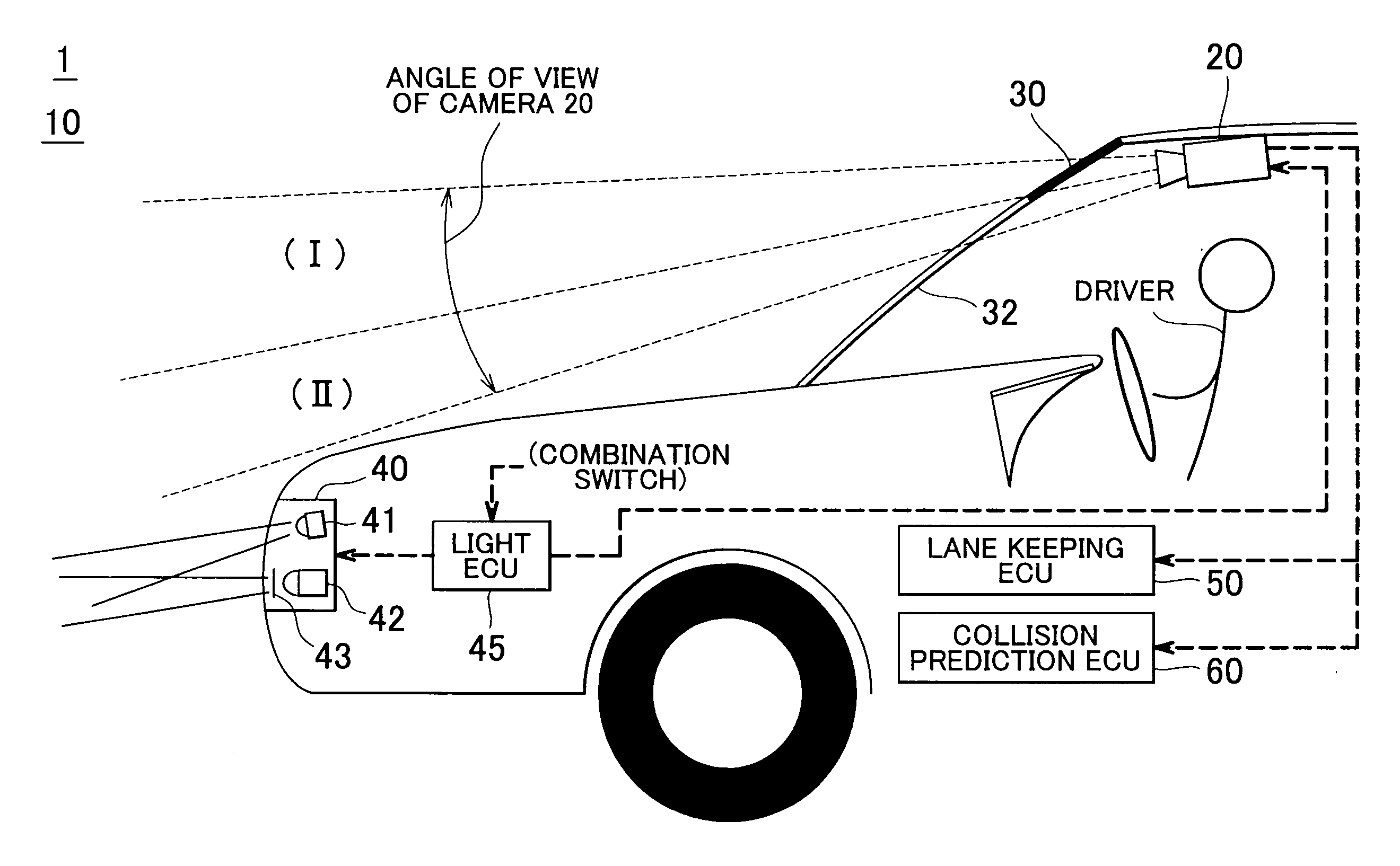
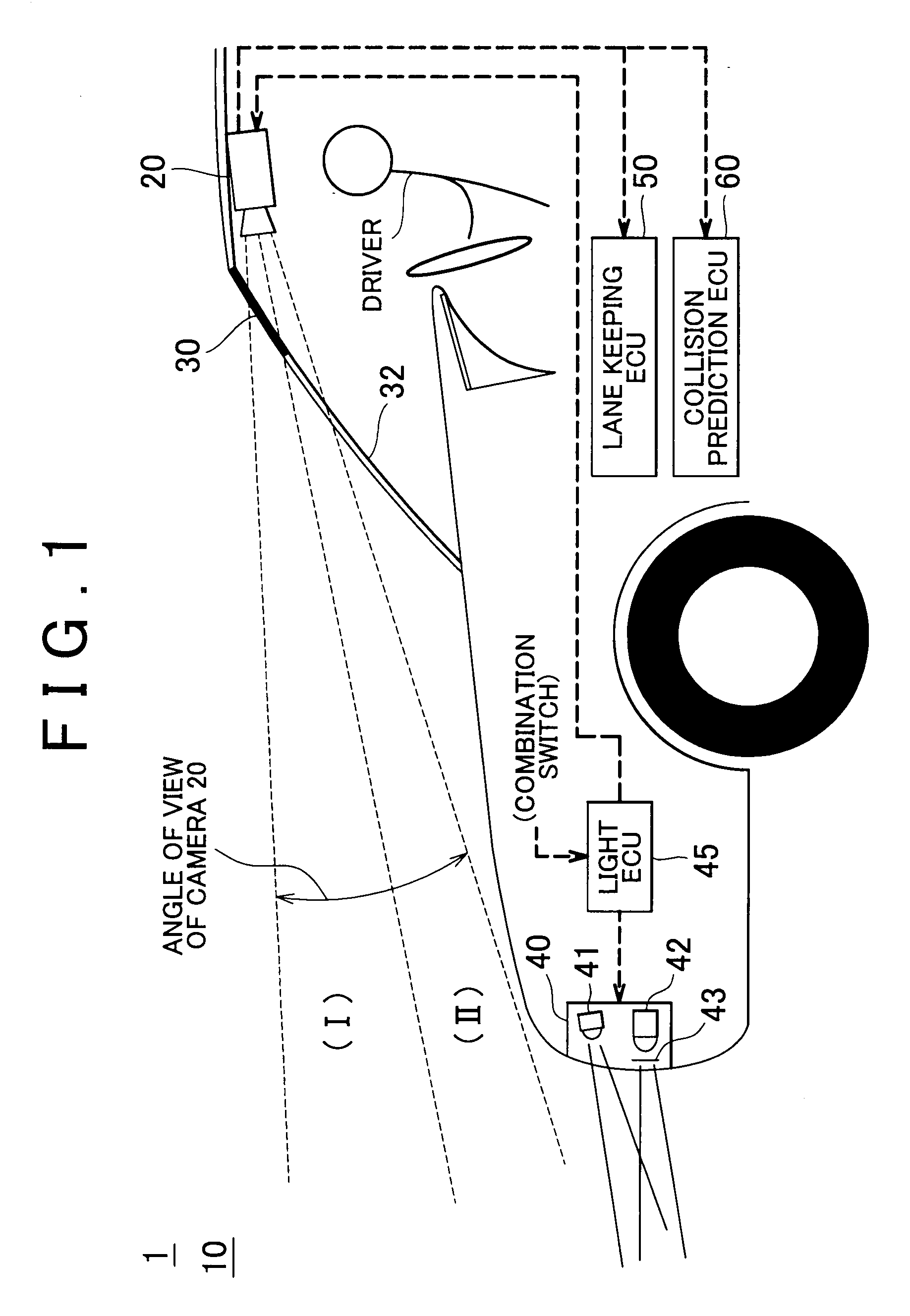
[0030]FIG. 1 is a diagram showing an example of an entire configuration of the vehicle control apparatus 1. The vehicle control apparatus 1 mainly includes the vehicle imaging system 10, a lane keeping ECU (Electronic Control Unit) 50, and a collision prediction ECU 60. In FIG. 1, the dashed line arrows indicate the flow of main information transmitted via wired or wireless communication.

[0031]The vehicle imaging system 10 includes a camera 20, a visible light cut filter 30, a head lamp assembly 40, and a light ECU 45.

[0032]For example, in the camera 20, a solid-state imaging device, such as a CCD (Charge Coupled Device), or a CMOS (Complementary Metal Oxide Semiconductor), is used. For example, ...


PUM


Abstract

A vehicle imaging system includes an imaging device that images at least a part of an area around a vehicle; and a visible light attenuation device that attenuates part of visible light that enters the imaging device. The imaging device includes an imaging element that converts both of the infrared light and an infrared ray to electric signals. The imaging device outputs both of image data produced based on the electric signal to which the visible light, which has entered the imaging device without passing through the visible light attenuation device, has been converted, and image data produced based on the electric signal to which the infrared ray, which has passed through the visible light attenuation device, has been converted.

Description

INCORPORATION BY REFERENCE[0001]The disclosure of Japanese Patent Application No. 2007-144088 filed on May 30, 2007 including the specification, drawings and abstract is incorporate herein by reference in its entirety.BACKGROUND OF THE INVENTION[0002]1. Field of the Invention[0003]The invention relates to a vehicle imaging system that images at least a part of an area around a vehicle, and outputs image data, and a vehicle control apparatus using the vehicle imaging system.[0004]2. Description of the Related Art[0005]Recently, a control system called, for example, LKA (Lane Keeping Assist), has been available. The control system detects the position of a road compartment line drawn or laid on a road, recognizes the positional relation between a host vehicle and a driving lane, and executes a control so that steering torque is automatically output to make the host vehicle travel without deviating from the driving lane (hereinafter, the control will be referred to as “lane keeping con...

Claims


Application Information

Patent Timeline
Patent Type & Authority Applications(United States)
IPC IPC(8): G08G1/01B60Q1/24B60R1/00B60R21/00B60R21/0134B60R21/34B60R21/36B60R21/38B60R22/46G08G1/16H04N7/18
CPCB60Q1/143G06K9/00805B60Q2300/056B60Q2300/41B60Q2300/45B60W40/02B60W40/072B60W40/076B60W2420/40B60W2420/403B60W2550/20B60W2550/402G06K9/00798G08G1/16B60Q9/008G08G1/166G08G1/167B60W2554/00B60W2556/50G06V20/588G06V20/58
Inventor USAMI, MASAYUKI
Owner TOYOTA JIDOSHA KK
Why Eureka
Try Eureka