Fuel cell system

Active Publication Date: 2008-12-04
HONDA MOTOR CO LTD
View PDF4 Cites 12 Cited by
  • Summary
  • Abstract
  • Description
  • Claims
  • Application Information

AI Technical Summary

Benefits of technology

[0024]According to the present invention, the fuel cell system sets the voltage threshold value or current threshold value in the low temperature range in which the voltage condition becomes severe to suppress the MEA degradation such as while warming up. Here, as the temperature characteristics related to the MEA degradation and the current versus voltage characteristics become stable in the temperature range after the warming up period, it is no longer necessary to set the threshold value according to the temperature, and then a constant output limit can be exe

Problems solved by technology

Therefore, for example, when the fuel cell is driven in the lower temperature state, the voltage lower limit becomes higher than the specified threshold value and there is a danger of entering the degradation range, despite the cell voltage being higher than the threshold value.
When the thresh

Method used


Image

  • Fuel cell system
  • Fuel cell system
  • Fuel cell system

Examples


Example

The First Embodiment

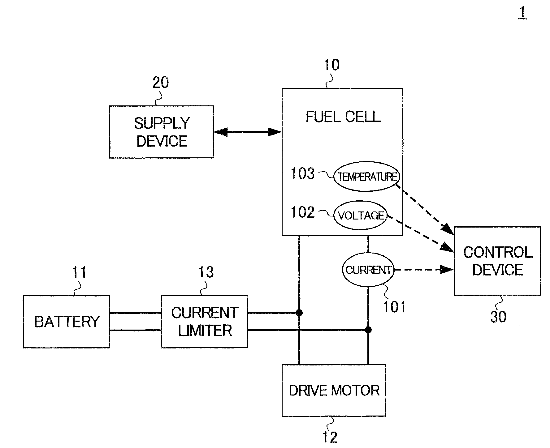
[0033]FIG. 1 shows a block diagram of a fuel cell system 1 of the first embodiment of the present invention. The fuel cell system 1 includes a fuel cell 10 that generates electric power by reacting hydrogen gas and air (oxidant gas) as reactant gas; a supply device 20 that supplies the hydrogen gas and the air to the fuel cell 10; a battery 11 as a storage means that can store the electric power; and a control device 30 that controls the fuel cell 10, the supply device 20 and the battery 11. Among these, the battery 11 and the fuel cell 10 are connected to a drive motor 12 that drives the fuel cell electric vehicle.

[0034]The fuel cell 10 generates electric power by the electrochemical reaction when the hydrogen gas is supplied to the anode (positive electrode) and the air, which includes oxygen, is supplied to the cathode (negative electrode).

[0035]The fuel cell 10 is connected to the battery 11 via a current limiter 13 and the drive motor 12. In addition, in the...

Example

The Second Embodiment

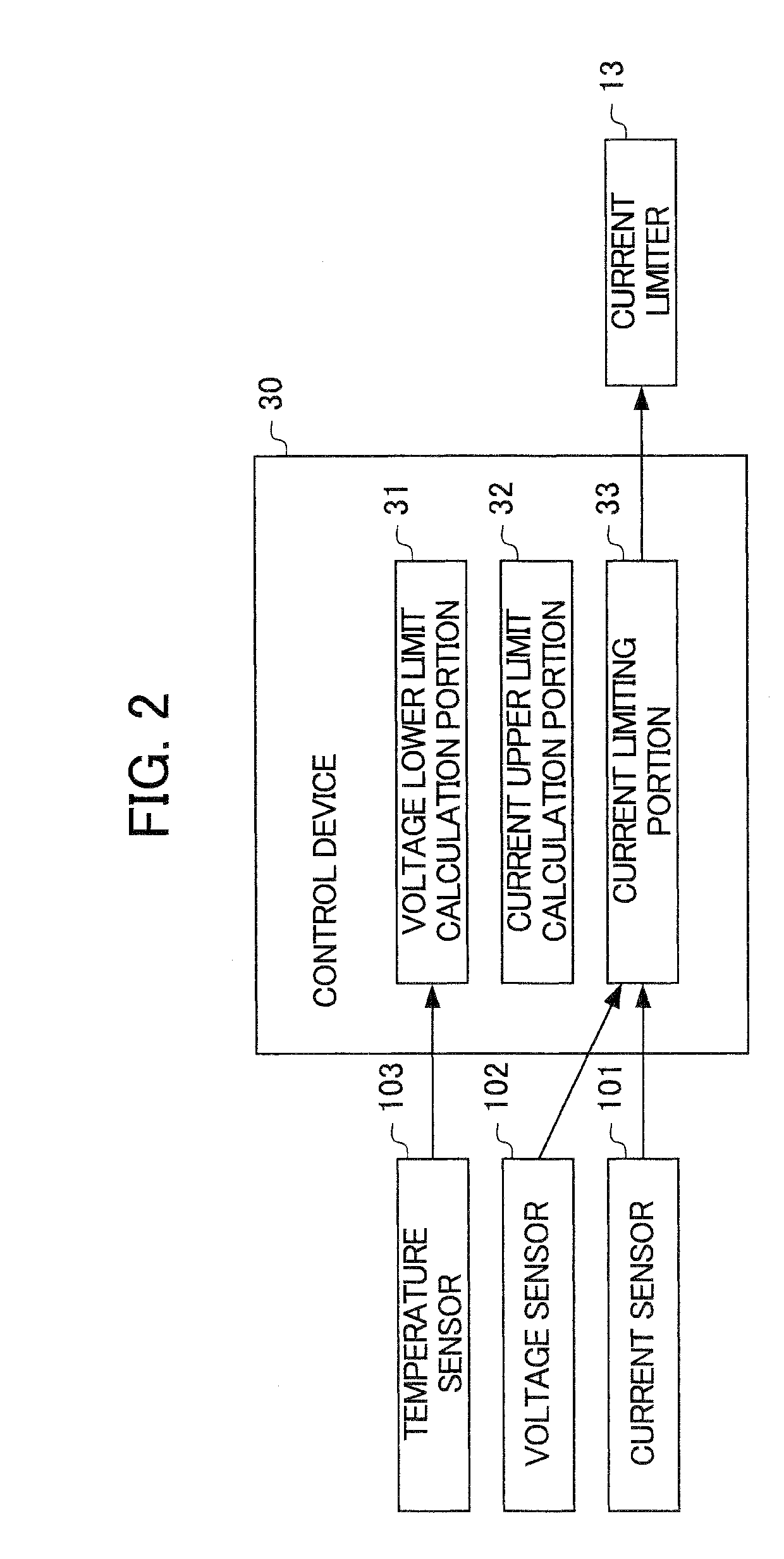
[0063]In this embodiment, the configuration of the voltage lower limit calculation portion 31, the current upper limit calculation portion 32 and the current limiting portion 33 are different from those of the first embodiment. Specifically, in the first embodiment, the voltage lower limit is used as the threshold value in the current limiting portion 33, but in the second embodiment, the current upper limit is used as the threshold value in the current limiting portion 33.

[0064]More specifically, in the first embodiment, the voltage lower limit is calculated as the voltage threshold by the voltage lower limit calculation portion 31. Then, the current upper limit calculation portion 32 calculates the current upper limit based on the voltage lower limit that is calculated by the voltage lower limit calculation portion 31. Next, the current limiting portion 33 limits the output current to be lower than the current upper limit in order to keep the lowest cell volta...


PUM


Abstract

A fuel cell system is provided that can suppress the degradation of the MEA and simultaneously assure the merchantability. The fuel cell system 1 includes: a fuel cell 10 that generates electric power by reacting hydrogen gas and oxidant gas; a temperature sensor 103 that detects the temperature of the fuel cell 10; a voltage lower limit calculation portion 31 that sets the voltage threshold to limit the output of the fuel cell10 based on the temperature detected of the fuel cell 10; a current upper limit calculation portion 32 and the current limiting portion 33 that limits the output of the fuel cell in a case where the voltage generated by the fuel cell 10 is lower than the voltage threshold.

Description

[0001]This application is based on and claims the benefit of priority from Japanese Patent Application No. 2007-147422, filed on 1 Jun. 2007, the content of which is incorporated herein by reference.BACKGROUND OF THE INVENTION[0002]1. Field of the Invention[0003]This invention relates to a fuel cell system. In particular, it relates to a fuel cell system mounted to an automobile.[0004]2. Related Art[0005]Recently, fuel cell systems have drawn attention as a new power source for automobiles. The fuel cell system includes, for example, a fuel cell that generates electric power by chemically reacting reactant gas, a reactant gas supplying device that supplies a reactant gas to the fuel cell via the reactant gas channel and a control device that controls the reactant gas supplying device.[0006]The fuel cell has, for example, a stack structure in which several tens to several hundreds of cell are laminated. Each cell is configured by sandwiching a membrane electrode assembly (MEA) by a p...

Claims


Application Information

Patent Timeline
IPC IPC(8): H01M8/04
CPCH01M8/0432H01M8/0488H01M8/0491H01M2250/20Y02T90/32Y02E60/50Y02T90/40
Inventor MIYATA, KOICHIROWAKE, CHIHIROOGAWA, JUMPEI
Owner HONDA MOTOR CO LTD
Why Eureka
Try Eureka