Construction Machine Control Mode Switching Device and Construction Machine

a technology of control mode switching and construction machine, which is applied in the direction of electric programme control, program control, instruments, etc., can solve the problems of difficult operation and exhaustion, and achieve the effect of simple arrangemen

Inactive Publication Date: 2008-12-04
KOMATSU LTD
View PDF7 Cites 54 Cited by
  • Summary
  • Abstract
  • Description
  • Claims
  • Application Information

AI Technical Summary

Benefits of technology

[0023]According to the above arrangement, since the actuator is provided by the hydraulic actuator and the respective driving means is provided by the hydraulic circuit, where the priority operation mode is executed by controlling the variable pressure-control valve provided in the hydraulic circuit, simple arrangement can be achieved.
[0024]In the control-mode switching device of a construction machine of the present invention, a noti

Problems solved by technology

However, such operation is v

Method used


Image

  • Construction Machine Control Mode Switching Device and Construction Machine
  • Construction Machine Control Mode Switching Device and Construction Machine
  • Construction Machine Control Mode Switching Device and Construction Machine

Examples


first embodiment

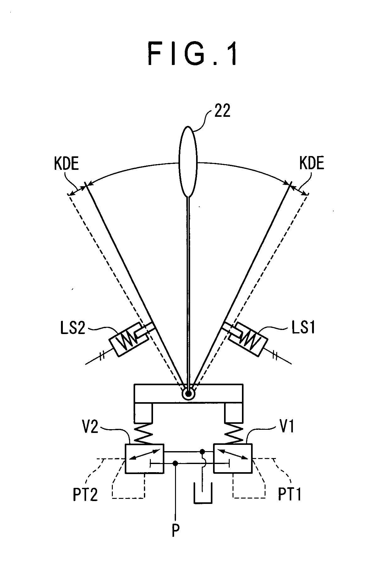
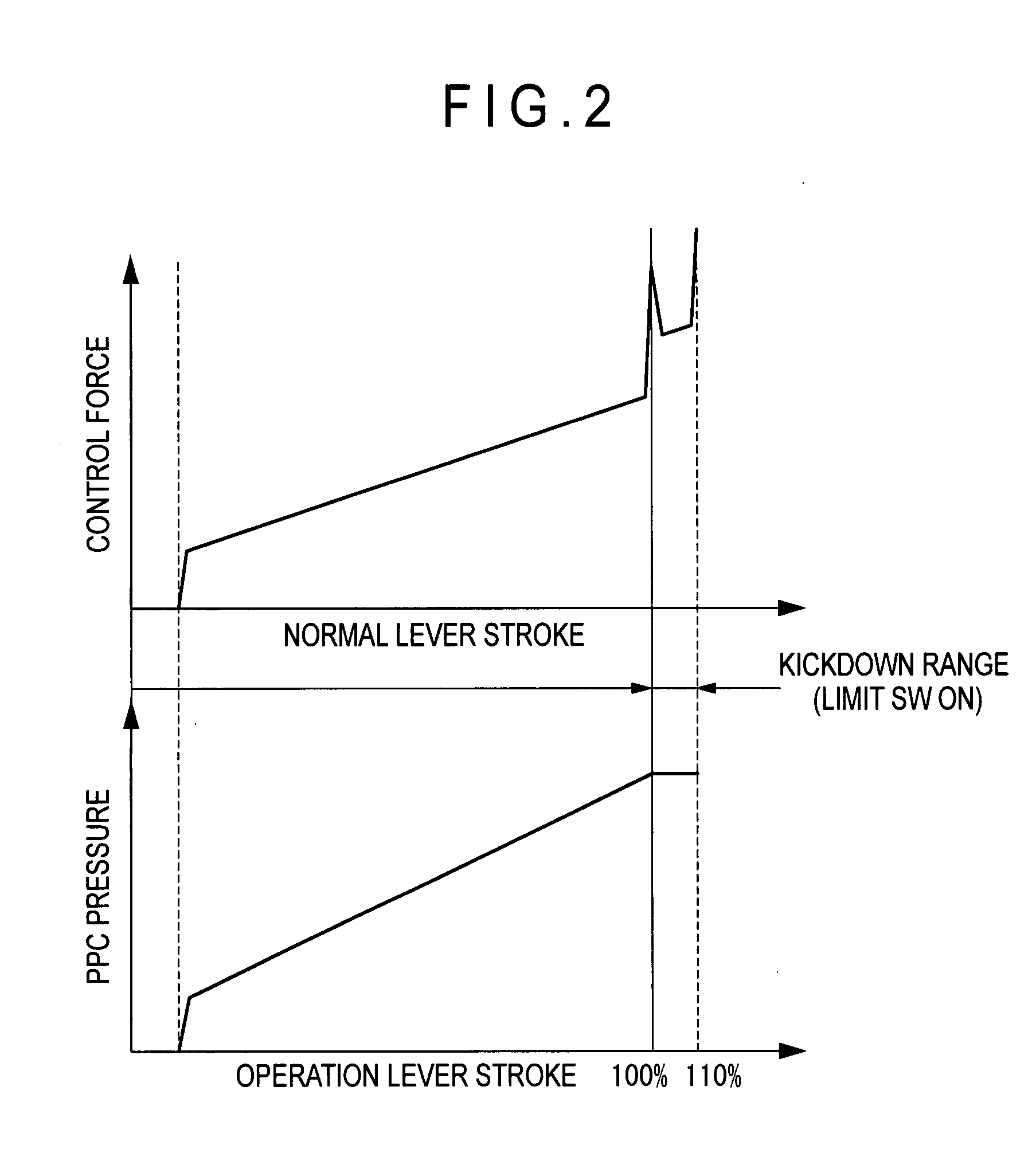
[0044]FIG. 1 is a schematic illustration of a control lever used in the present embodiment. FIG. 2 is an illustration showing output characteristics of control force of the control lever and PPC (Pilot Pressure Control) pressure.

[0045]A control lever 22 opens valves V1 and V2 in accordance with operating direction and angle, so that pressure oil from a pilot pump P is fed into pilot lines PT1 and PT2 through the valves V1 and V2.

[0046]When the stroke range of a normal control lever is 100%, the control lever 22 can be operated to around 110%. When the operation stroke of the control lever 22 exceeds 100%, an operation feeling is given where the lever does not move without applying further greater control force. For instance, when the operation stroke of the control lever 22 exceeds 100%, movable part of the control lever 22 touches a biasing unit such as a spring, so that a control force greater than the previous control force is required for moving the lever on account of the react...

second embodiment

[0146]FIG. 8 shows a hydraulic control circuit of a hydraulic excavator according to second embodiment of the invention. The hydraulic control circuit of the present embodiment differs from the hydraulic control circuit of the first embodiment in the following.

[0147]The PPC type control levers 22a, 22b and 22c, the limit switches 72a, 72c and 72d, the main line 20 and the pilot lines 73a, 73b, 73c, 73d, 73e and 73f are omitted from the first embodiment and electric control levers 22d, 22e and 22f are provided in place thereof. In this connection, pilot valves (electromagnetic proportional control valve) 25a, 25b, 25c, 25d, 25e and 25f are provided to the controller 23 via signal circuits 24a, 24b, 24c, 24d, 24e and 24f, the pilot valves 25a, 25b, 25c, 25d, 25e and 25f being connected to both ends of the pressure compensated flow-control valves 12, 15 and 16.

[0148]As shown in FIGS. 9 and 10, the electric control levers 22d, 22e and 22f are manipulable to a range approximately 110% (k...

third embodiment

[0151]FIG. 11 shows a control system circuit of an electric excavator according to third embodiment of the invention. The control system circuit of the present embodiment differs from the hydraulic control circuit of the first embodiment in the following.

[0152]In the second embodiment, instead of the swing actuator (swing hydraulic motor 2), the pressure compensated flow-control valve 15 of the swing hydraulic motor 2, the boom actuator (boom cylinder 6), the pressure compensated flow-control valve 12 of the boom cylinder 6, the arm actuator (arm cylinder 7) and the pressure compensated flow-control valve 16 of the arm cylinder 7, a swing actuator (swing electric motor 102), an inverter 115 of the swing electric motor 102, a boom actuator (boom cylinder device 106), an inverter 112 of the boom cylinder device 106, an arm actuator (arm cylinder device 107) and an inverter 116 of the arm cylinder device 107 are provided. A battery 110 and a capacitor (electrical condenser) 113 that is...


PUM


Abstract

A control-mode switching device includes: a plurality of actuators (2, 6, 7) that conduct different movement; driving means (10, 11, 12, 13, 14, 15) that drive the actuators; a plurality of control levers (22a-22c) that command operation of the driving means; a plurality of limit switches (72a-72e) that detect arrival of the control levers to the proximity of an end of a control range; a mode judging means (controller 23) that judges whether a priority operation mode is taken or not in accordance with a combination of on/off conditions of the limit switches; and a drive controlling means (controller 23) that, when it is judged by the mode judging means that the priority operation mode is taken, controls the driving means so that an output of selected one or more of the driving means becomes larger than that in a normal mode or the power ratio as compared with the other driving means becomes larger.

Description

TECHNICAL FIELD[0001]The present invention relates to a control-mode switching device of a construction machine and a construction machine. More specifically, it relates to a control-mode switching device and a construction machine that are capable of easily switching the operation modes of a construction machine such as an excavator.BACKGROUND ART[0002]A hydraulic excavator as shown in FIGS. 13A and 13B is known as a construction machine for excavating and loading earth and sand, which includes: a traveling hydraulic motor 1 for traveling a lower traveling body a; a swing hydraulic motor 2 for swinging an upper swing body b; work equipments c (a boom 3, an arm 4 and a bucket 5) mounted on the front side of the upper swing body b; and a boom cylinder 6, arm cylinder 7 and bucket cylinder 8 for driving the work equipments c.[0003]The hydraulic excavator performs a sequence of operations during an excavating process such as excavation, lift-up swing, earth removal and lift-down swing....

Claims


Application Information

Patent Timeline
IPC IPC(8): E02F9/20E02F9/22E02F9/26
CPCE02F9/2025E02F9/2225E02F9/2228E02F9/2235E02F9/2285E02F9/2292E02F9/2296E02F9/26Y10S37/902E02F9/2004E02F9/22
Inventor KANAYAMA, NOBORUSASANO, KOUTAROUKAWAMURA, KOICHI
Owner KOMATSU LTD
Why Eureka
Try Eureka