Eureka AIR delivers breakthrough ideas for toughest innovation challenges, trusted by R&D personnel around the world.

Liquid discharge apparatus

Inactive Publication Date: 2008-12-11
FUJIFILM CORP
View PDF3 Cites 10 Cited by
  • Summary
  • Abstract
  • Description
  • Claims
  • Application Information

AI Technical Summary

Benefits of technology

[0021]In view of the foregoing circumstances, it is an object of the present invention to provide a liquid discharge apparatus including a piezoelectric body that has excellent mechanical durability and excellent piezoelectric performance.
[0055]In the liquid discharge apparatus of the present invention, the piezoelectric body is structured in such a manner that the fracture stress of the edge portion (a portion including at least a portion on the outside of the wall position of the liquid storage chamber) of the piezoelectric body is higher than that of the main portion of the piezoelectric body. In the piezoelectric body, stress tends to be applied to the edge portion, which is constrained by the liquid storage-discharge member, and piezoelectric deformation should efficiently occur in the main portion. It is possible to form the piezoelectric body in which the fracture stress of the edge portion is higher than that of the main portion, for example, by forming the piezoelectric body in such a manner that an average crystal diameter of the edge portion is smaller than that of the main portion. Alternatively, it is possible to form the piezoelectric body in which the fracture stress of the edge portion is higher than that of the main portion by forming the piezoelectric body in such a manner that the edge portion has composition that can cause the Young's modulus of the edge portion to become lower than that of the main portion.
[0056]Further, in the liquid discharge apparatus of the present invention, the edge portion of the piezoelectric body and the main portion thereof are formed on different base layers from each other. Therefore, it is possible to form a piezoelectric body including the edge portion and the main portion that have different properties from each other, even if the edge portion and the main portion are formed in the same process. Further, in the method disclosed in Japanese Unexamined Patent Publication No. 2005-349714, amorphous structure is formed before forming desirable structure. However, in the liquid discharge apparatus of the present invention, the main portion of the piezoelectric body, in which piezoelectric deformation must efficiently occur, can be formed without forming amorphous structure. Further, it is possible to form the main portion of the piezoelectric body in such a manner that the main portion has high crystal orientation.
[0057]Therefore, the present invention can provide a liquid discharge apparatus including a piezoelectric body that has excellent mechanical durability and excellent piezoelectric performance.

Problems solved by technology

Therefore, if the inkjet-type recording head is used for long time, there is a risk that the mechanical durability of the piezoelectric body is lost because the piezoelectric body is repeatedly driven in such a manner that displacement of the piezoelectric body occurs.
Therefore, there is a risk that the durability of the vibration plate is lost in long time.
Hence, it is not desirable that the piezoelectric body is formed in such a manner.
However, in the method of polycrystallizing the piezoelectric material after temporarily forming amorphous structure, it is difficult to obtain high crystal orientation.
Hence, it is difficult to achieve excellent piezoelectric performance.

Method used


Image

  • Liquid discharge apparatus
  • Liquid discharge apparatus
  • Liquid discharge apparatus

Examples


first embodiment

of Inkjet-Type Recording Head (Liquid Discharge Apparatus)

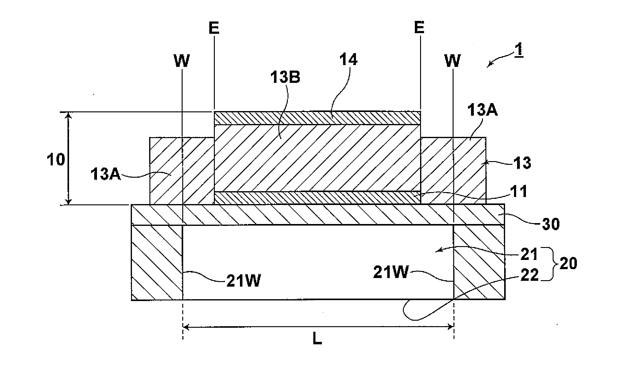
[0066]The structure of an inkjet-type recording head according to a first embodiment of the present invention will be described with reference to attached drawings. FIG. 1 is a cross-sectional diagram illustrating a major part of the inkjet-type recording head. In FIG. 1, elements of the inkjet-type recording head are illustrated in appropriate scale, which is different from actual scale, so that they are easily recognized.

[0067]An inkjet-type recording head (liquid discharge apparatus) 1 includes an ink nozzle (liquid storage-discharge member) 20. Further, the ink nozzle 20 includes an ink chamber (liquid storage chamber) 21 for storing ink and an ink outlet (liquid outlet) 22 for discharging (jetting) the ink from the ink chamber 21 to the outside of the ink chamber 21. A vibration plate 30 is provided on the ink nozzle 20. Further, a piezoelectric element 10 including a lower electrode 11, a piezoelectric body 13 and an up...

second embodiment

of Inkjet-Type Recording Head (Liquid Discharge Apparatus)

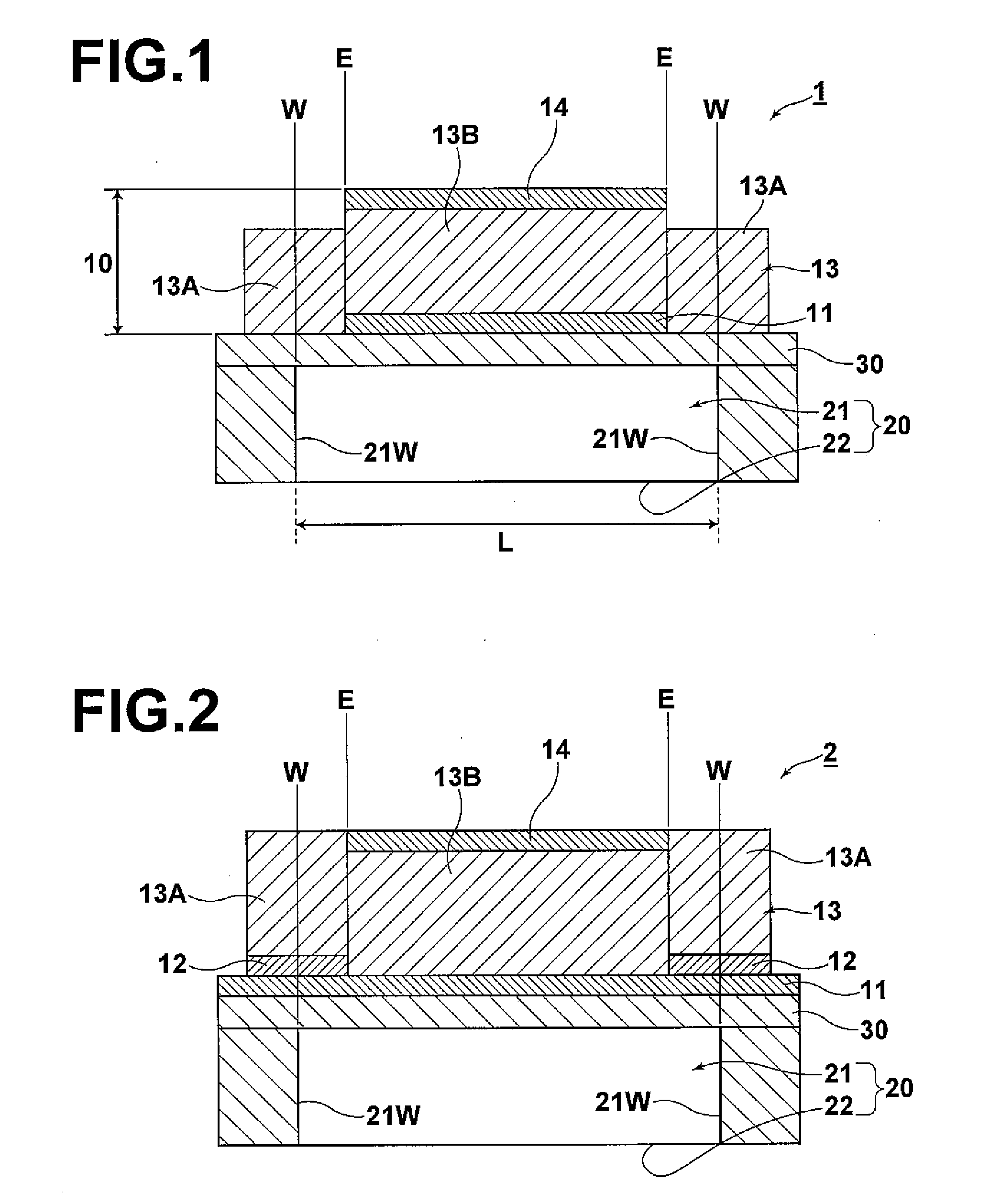
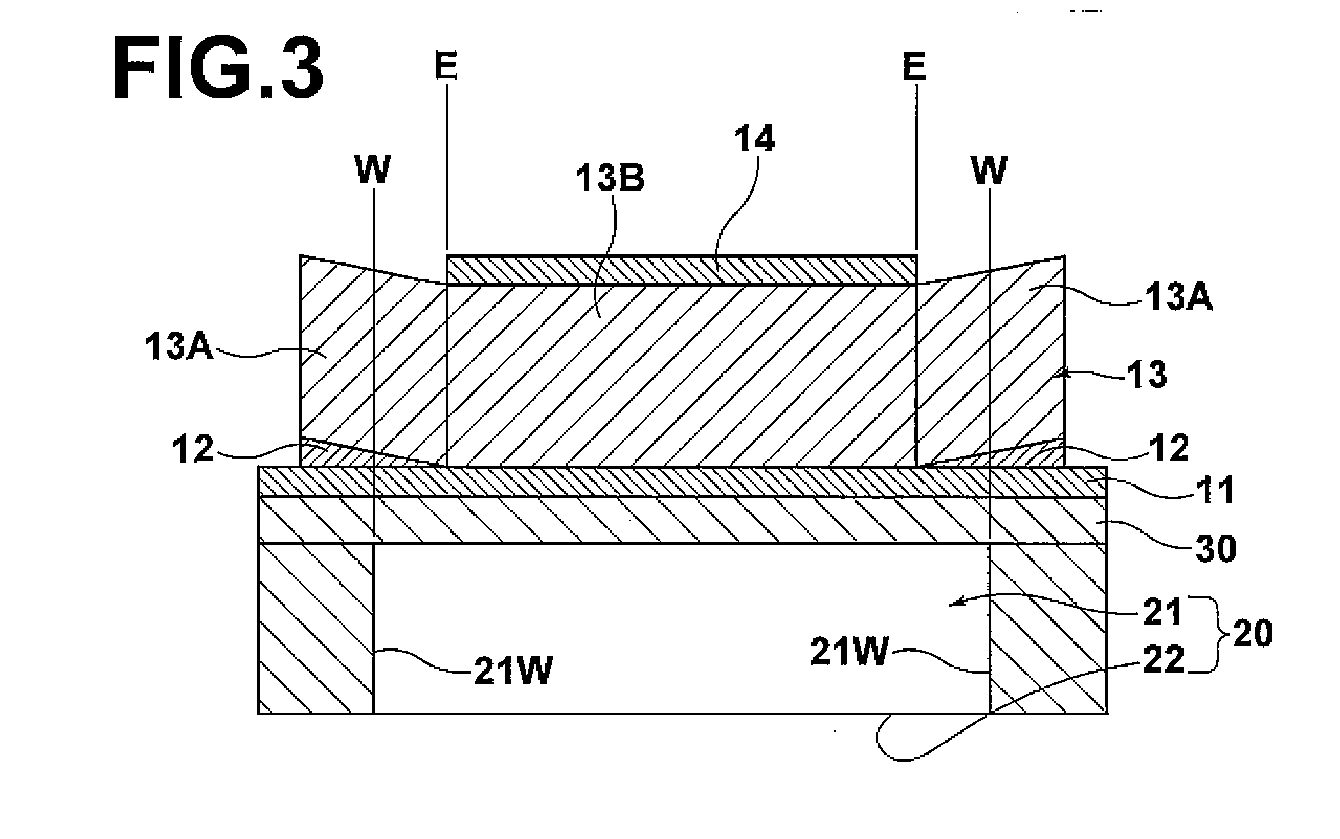
[0100]With reference to the attached drawings, the structure of an inkjet-type recording head according to the second embodiment of the present invention will be described. FIG. 2 is a cross-sectional diagram corresponding to FIG. 1, which illustrates the inkjet-type recording head according to the first embodiment of the present invention. In FIG. 2, the same reference numerals as those of the first embodiment will be used for the corresponding elements and explanation thereof will be omitted.

[0101]The basic structure of an inkjet-type recording head (liquid discharge apparatus) 2 according to the present embodiment is similar to that of the inkjet-type recording head according to the first embodiment. However, in the inkjet-type recording head 2 according to the present embodiment, the lower electrode 11 is evenly formed in the entire area of the substrate. Further, a crystal grain diameter control layer 12, as the base lay...

example 1

[0138]An ink chamber was formed by performing reactive ion etching on the back side of a Si single-crystal substrate. Then, a vibration plate and an ink nozzle having open pool structure were formed by processing the substrate itself. The ink nozzle includes an ink chamber and an ink outlet. The thickness of the vibration plate is approximately 10 μm. Further, the thickness of the ink chamber is approximately 500 μm and the width of the ink chamber is 300 μm.

[0139]Next, a lower electrode was formed by patterning by using a lift off method. Specifically, a photoresist was formed on a surface of the substrate by patterning by using a photolithography method. The photoresist was formed by patterning only in an area corresponding to an edge portion of a piezoelectric member, which would be formed later. Then, the lower electrode was evenly deposited on the entire area of the substrate by using a sputtering method. The lower electrode has layered structure in which a Ti layer that has a ...


PUM


Abstract

A liquid discharge apparatus includes a liquid storage-discharge member having a liquid storage chamber for storing liquid and a liquid outlet for discharging the liquid from the liquid storage chamber to the outside of the liquid storage chamber, a vibration plate formed on the liquid storage-discharge member and a piezoelectric element having a lower electrode, a piezoelectric body and an upper electrode, which are sequentially formed on the vibration plate. The piezoelectric body includes an edge portion including at least a portion of the piezoelectric body, the portion positioned on the outside of the wall position of the liquid storage chamber, and a main portion, which is the remaining portion of the piezoelectric body. Further, the edge portion and the main portion are formed on different base layers from each other and the fracture stress of the edge portion is higher than that of the main portion.

Description

BACKGROUND OF THE INVENTION[0001]1. Field of the Invention[0002]The present invention relates to a liquid discharge apparatus that includes a liquid storage-discharge member having a liquid storage chamber for storing liquid and a liquid outlet for discharging the liquid from the liquid storage chamber to the outside of the liquid storage chamber, a vibration plate formed on the liquid storage-discharge member and a piezoelectric element having a lower electrode, a piezoelectric body and an upper electrode, the lower electrode, the piezoelectric body and the upper electrode being sequentially formed on the vibration plate.[0003]2. Description of the Related Art[0004]A piezoelectric element including a piezoelectric body and electrodes for applying an electric field to the piezoelectric body is used as an actuator that is mounted in a liquid discharge apparatus, such as an inkjet-type recording head, or the like. The piezoelectric body, which has a piezoelectric characteristic, expan...

Claims


Application Information

Patent Timeline
IPC IPC(8): B41J2/045
CPCB41J2/14233B41J2/161B41J2/1628B41J2/1631B41J2/1646
Inventor NIHEI, YASUKAZU
Owner FUJIFILM CORP
Why Eureka
Eureka Blog
Learn More