
Optical screening device

a screening device and optical technology, applied in the field of optical screening devices, can solve the problems of time-consuming and laborious, unpleasant treatment, disfiguring and often ineffective process of taking biopsy tissue samples,

Inactive Publication Date: 2008-12-11
FRIEDMAN JOSHUA
View PDF4 Cites 10 Cited by
  • Summary
  • Abstract
  • Description
  • Claims
  • Application Information

AI Technical Summary

Problems solved by technology

When diagnosed late the treatment is unpleasant, disfiguring and often not effective.
As in all cancers, a biopsy is used to make a positive diagnosis; however the process of taking a biopsy tissue sample is time consuming, costly and painful.
However, it does not work for all lesions and does not delineate the border between healthy and pre-cancerous or dysplastic or cancerous tissue.
Moreover, since a metal halide light source provides most of its energy outside the useful wavelength spectrum for this procedure, this device is complex, unnecessarily large, bulky and extremely expensive.

Method used


Image

  • Optical screening device
  • Optical screening device
  • Optical screening device

Examples


Embodiment Construction

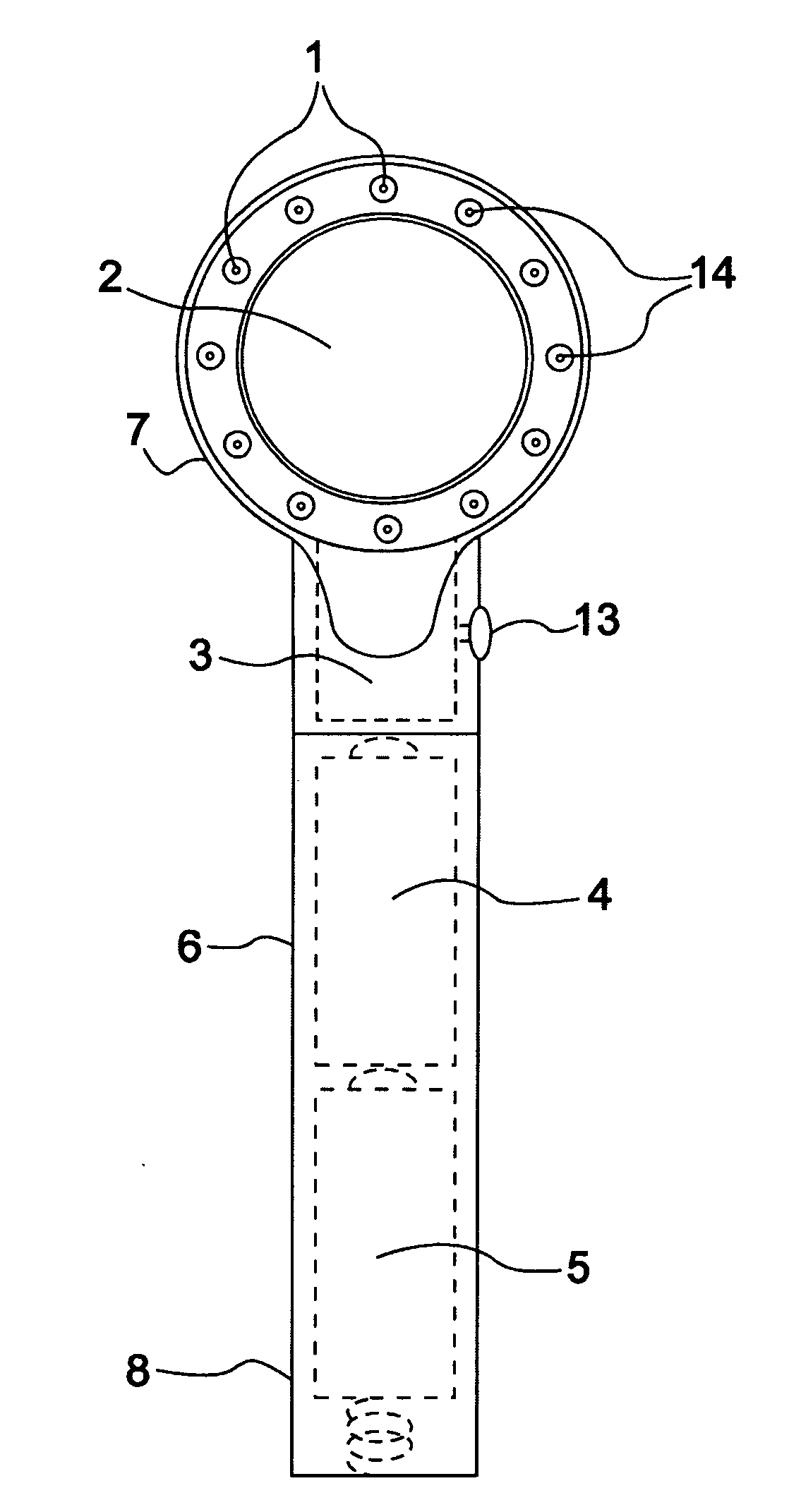
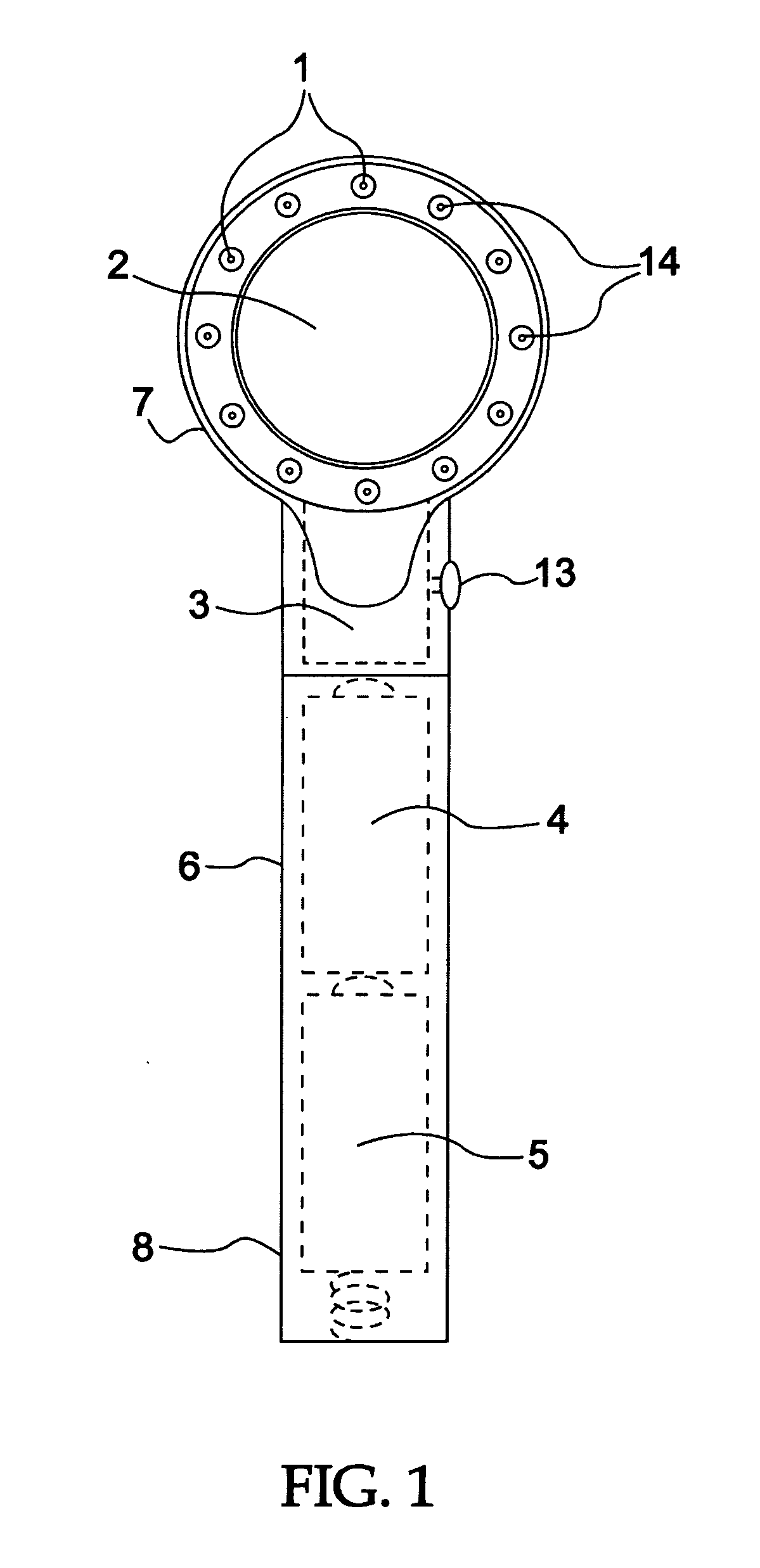
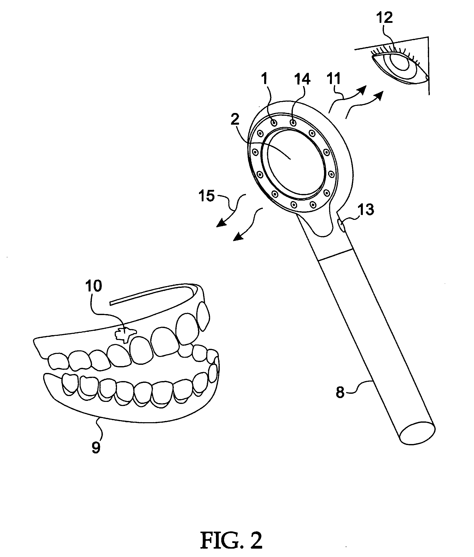
[0024]The optical screening device of the present invention is illustrated in FIGS. 1-4 represented by a simple hand held device 8 including a handle 6 and a head 7 extending from the handle 6. The head 7 defines a housing in which an array of light emitting diode's (LED's) 1 is mounted. A power source 4 or 5 for the array of light emitting diode's (LED's) 1, which may include one or more batteries, is preferably located in the handle 6. Light emitting diodes are low in cost and have lower power requirements due to their high efficiency. A single filter 2, preferably a high pass filter as is known to those skilled in the art or a bandpass filter, is supported by the device 8 at a location adjacent to the array of LED's 1 so that a substantial amount of the irradiated light reflected from skin tissue to be observed by the screening device 8 will primarily pass through the filter 2. Thus the filter simultaneously acts as a viewing area for the optical sensing device 8 as well as to bl...


PUM


Abstract

An optical screening device for detecting abnormal skin tissue indicative of disease including a handle having an elongated stem adapted for holding the optical screening device in one hand and a head for housing an array of light emitting diodes with each diode in the array being spaced apart to form a given geometry with each diode selected to emit light in a wavelength range between 340 nm to 470 nm; a high pass filter supported by said handle in close proximity to said array of light emitting diodes with the filter being of a size to provide a defined viewable area for visibly detecting irradiated light reflected from skin tissue under observation and adapted to block light at least below 400 nm; and a source of electrical power for energizing said array of light emitting diodes.

Description

FIELD OF INVENTION [0001]This is a continuation-in-part of U.S. patent application Ser. No. 11 / 811,580 filed Jun. 11, 2007 to an optical screening device for detecting abnormal skin tissue in a mammal and particularly in the mouth indicative of disease such as cancer or a pre-cancerous oral tissue.BACKGROUND [0002]Oral cancer affects over 30,000 people today in the U.S. alone. The treatment for this disease is most effective when diagnosed early. When diagnosed late the treatment is unpleasant, disfiguring and often not effective. Advanced oral cancer is treated with surgery, chemo and radiation much the same as other aggressive cancers.[0003]The early signs of oral cancer are not always discernable upon visual examination. In an attempt to improve the visualization other modalities have been developed to assist in screening for cancer and pre-cancerous lesions. Some of these procedures involve the use of toluidine blue rinse, acetic acid rinse and biofluorescence.[0004]As in all ca...

Claims


Application Information

Patent Timeline
Patent Type & Authority Applications(United States)
IPC IPC(8): A61B1/07A61B1/24
CPCA61B1/0676A61B1/0684A61B1/07A61B1/24A61B5/0088A61B1/0607
Inventor FRIEDMAN, JOSHUA
Owner FRIEDMAN JOSHUA
Learn More