

Cooling system for cryogenic storage container and operating method therefor
a cryogenic storage container and cooling system technology, applied in the direction of superconducting magnets/coils, magnetic bodies, instruments, etc., can solve the problems of difficult application of cryogenic freezer to living body magnetic measurement, affecting sensitivity, and generating vibrations in cryogenic freezers, etc., to achieve the effect of suppressing the amount of liquid helium evaporation
- Summary
- Abstract
- Description
- Claims
- Application Information
AI Technical Summary
Benefits of technology
Problems solved by technology
Method used
Image

Examples
embodiment 1
[0056]FIG. 3 shows the rough configuration of the cooling system for a cryogenic storage container according to the present invention. The cooling system for a cryogenic storage container according to the present invention is configured by a storage unit 100, a cooling source 101, and a transport piping 102. The cooling source 101 is equipped with a cryogenic freezer not shown in the attached drawings. The cryogenic freezer is coupled to a compressor not shown in the attached drawings via high pressure piping. Using the cryogenic freezer eliminate the necessity to supply a coolant such as liquid nitrogen, liquid helium, etc. In addition, the coolness at or lower than the temperature of liquid nitrogen occurring in the cooling stage of the cryogenic freezer can be used.
[0057]In FIG. 3, a bellows unit 104 is provided for a part of the transport piping 102. In the bellows unit 104, the bellows unit 104 is fixed to the floor using a support table 105 at any portion of the bellows unit 1...
embodiment 2
[0089]FIG. 7 shows another example of a path for cooling a heat shield provided in the storage unit 100 using a coolant cooled at a cryogenic temperature by the cooling source 101. The entire configuration is the same as shown in FIG. 3. The structure of the storage unit 100 is also the same as the structure shown in FIG. 1. The structure of the cooling source 101 is the same as the structure shown in FIG. 5. The structure of the transport piping 102 is the same as the structure shown in FIG. 8.
[0090]The helium gas cooled down to the same temperature as the second cooling stage 32 of the cryogenic freezer 30 by the heat exchange unit 42 thermally coupled to the second cooling stage 32 of the cryogenic freezer 30 in the cooling source 101 is delivered to the storage unit 100 through the coolant piping 11a, and cools the heat shield 7 in the two provided heat shields between the storage container 2 and the vacuum container 3 in the vacuum tank 10. Since there is the high temperature s...
embodiment 3
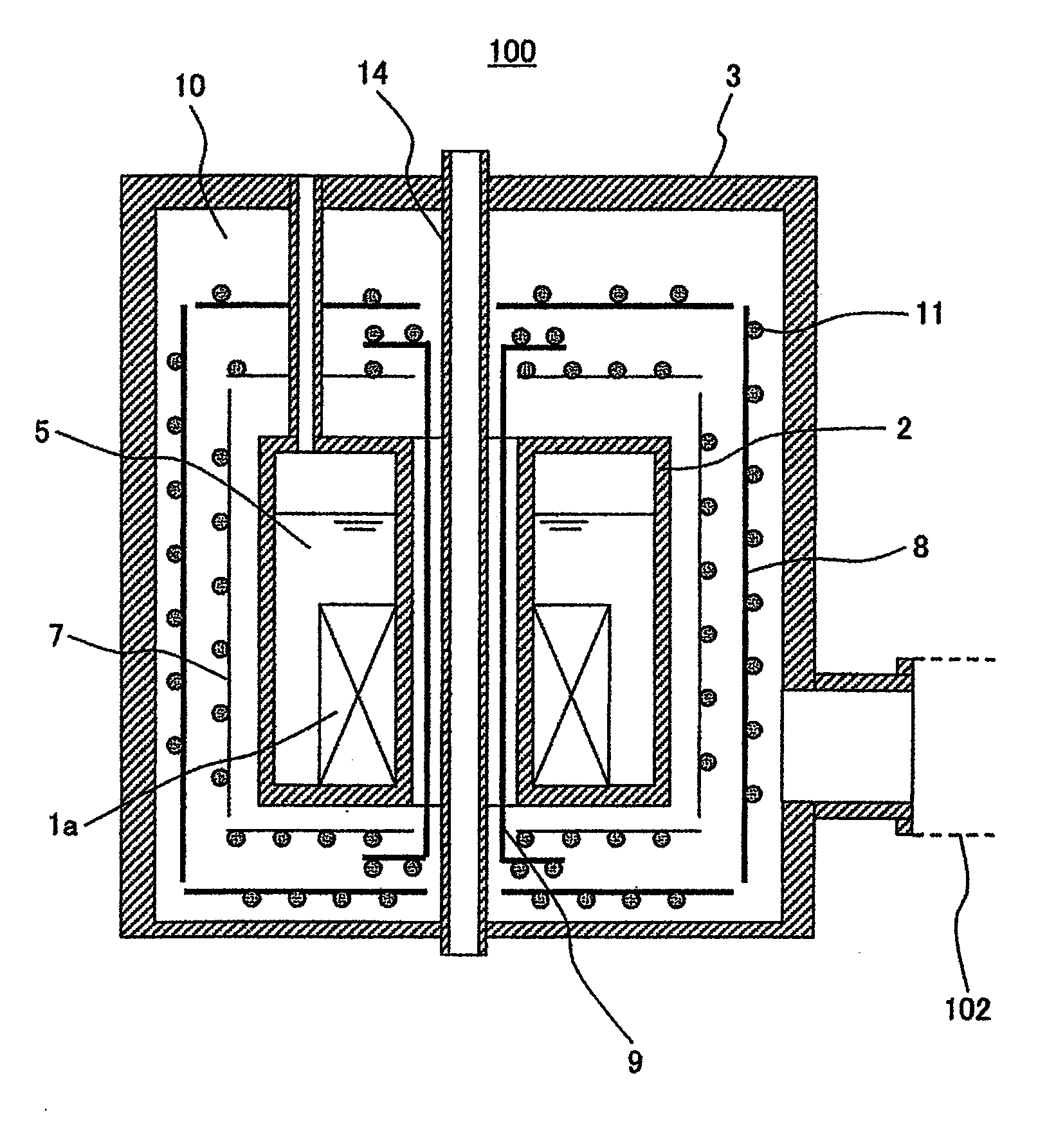
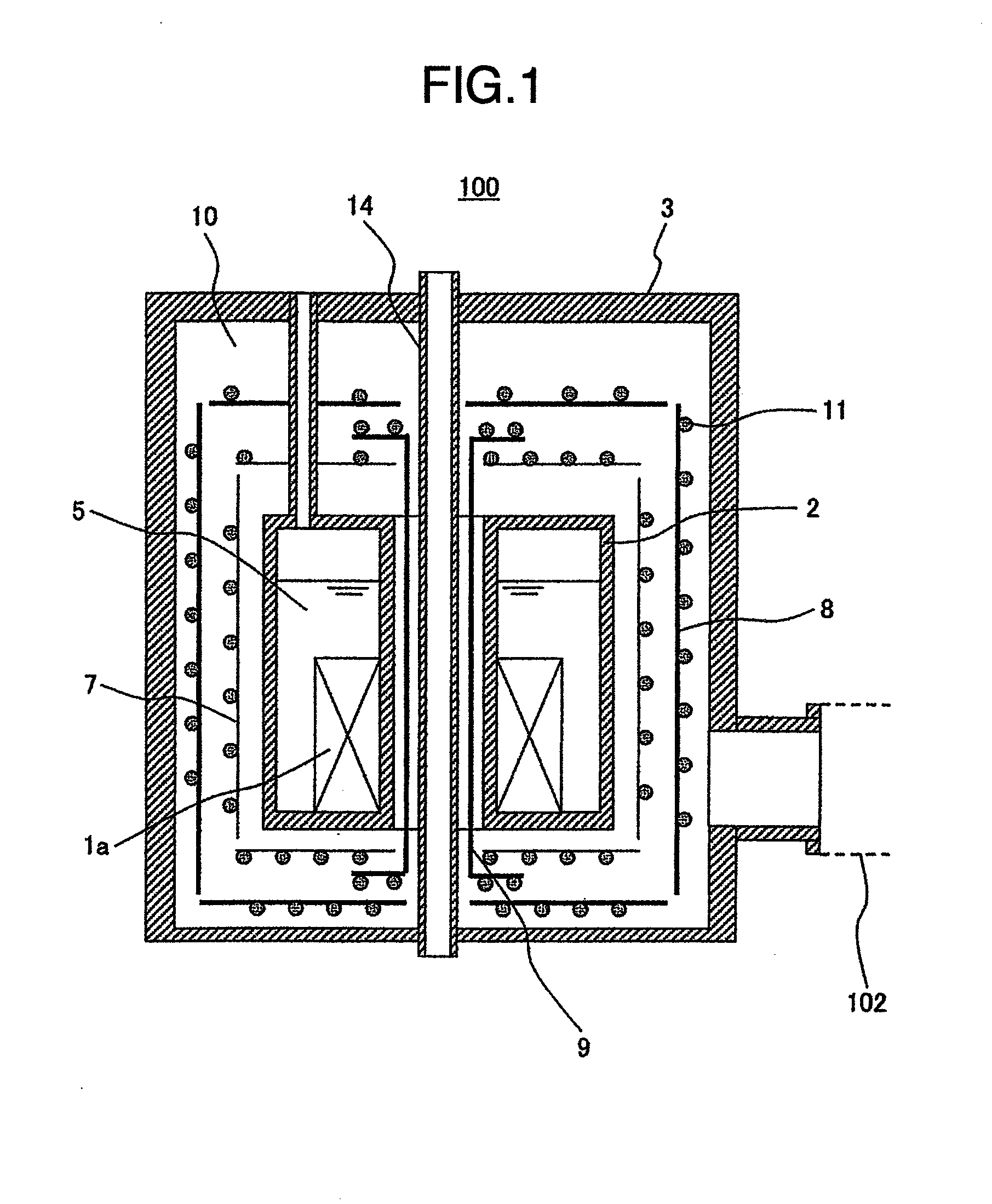
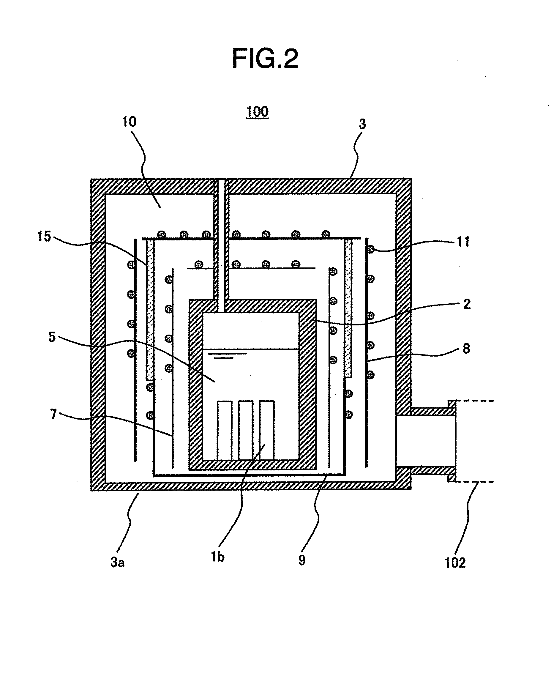
[0097]FIG. 2 is a sectional view of the storage unit of the cryogenic storage container storing a superconductive device. The entire configuration of the cryogenic storage container is the same as the configuration shown in FIG. 3. The structure of the cooling source is the same as the structure shown in FIG. 5. The path for circulating a coolant can be any of the circulation paths shown in FIGS. 5 and 6. The structure of the transport piping is the same as the structure shown in FIG. 8.
[0098]In the present invention, the superconductive device refers to, for example, a superconducting quantum interference device (SQUID) for measuring a weak magnetic field. The SQUID is a high sensitive magnetic sensor capable of measuring a weak magnetic field of 1 / 1,000,000 or less of the earth's magnetic field. To realize a high sensitive measurement, it is necessary to reduce the thermal noise occurring from the SQUID itself. Therefore, liquid helium is used for cooling at a cryogenic temperatur...
PUM
 Abstract
Description
Claims
Application Information