Broadcast Signal Receiving Apparatus

a technology for receiving apparatuses and broadcast signals, applied in electrical apparatus, continuous tuning, resonance circuit tuning, etc., can solve problems such as difficult impedance matching and easy interference, and achieve excellent selectivity of target frequencies and easy impedance matching

Inactive Publication Date: 2008-12-18
NEURO SOLUTION CORP
View PDF3 Cites 3 Cited by
  • Summary
  • Abstract
  • Description
  • Claims
  • Application Information

AI Technical Summary

Benefits of technology

[0015]According to the present invention having the above configuration, the variable band-pass filter is used so that a variable tuning circuit exhibiting a high Q-value is configured without using any transformer and varactor diode, and thus the integration in an IC chip is easily performed and further the selectivity of a target frequency is made excellent.
[0016]According to another feature of the present invention, the impedance as seen from the loop antenna side to the IC chip side is equal to the reciprocal of a conductance of the MOS transistor and thus is simplified, so that impedance matching can be easily achieved.

Problems solved by technology

Accordingly, the selectivity of a target frequency (the capability of eliminating an interfering signal of another frequency when the interfering signal is applied while a signal of a target frequency is received) is low, resulting in a problem of being susceptible to interferences.
Further, when the LNA is arranged closest to the reception antenna to omit a transformer, impedance conversion by the transformer cannot be implemented, so impedance matching is difficult to achieve.

Method used


Image

  • Broadcast Signal Receiving Apparatus
  • Broadcast Signal Receiving Apparatus
  • Broadcast Signal Receiving Apparatus

Examples


Embodiment Construction

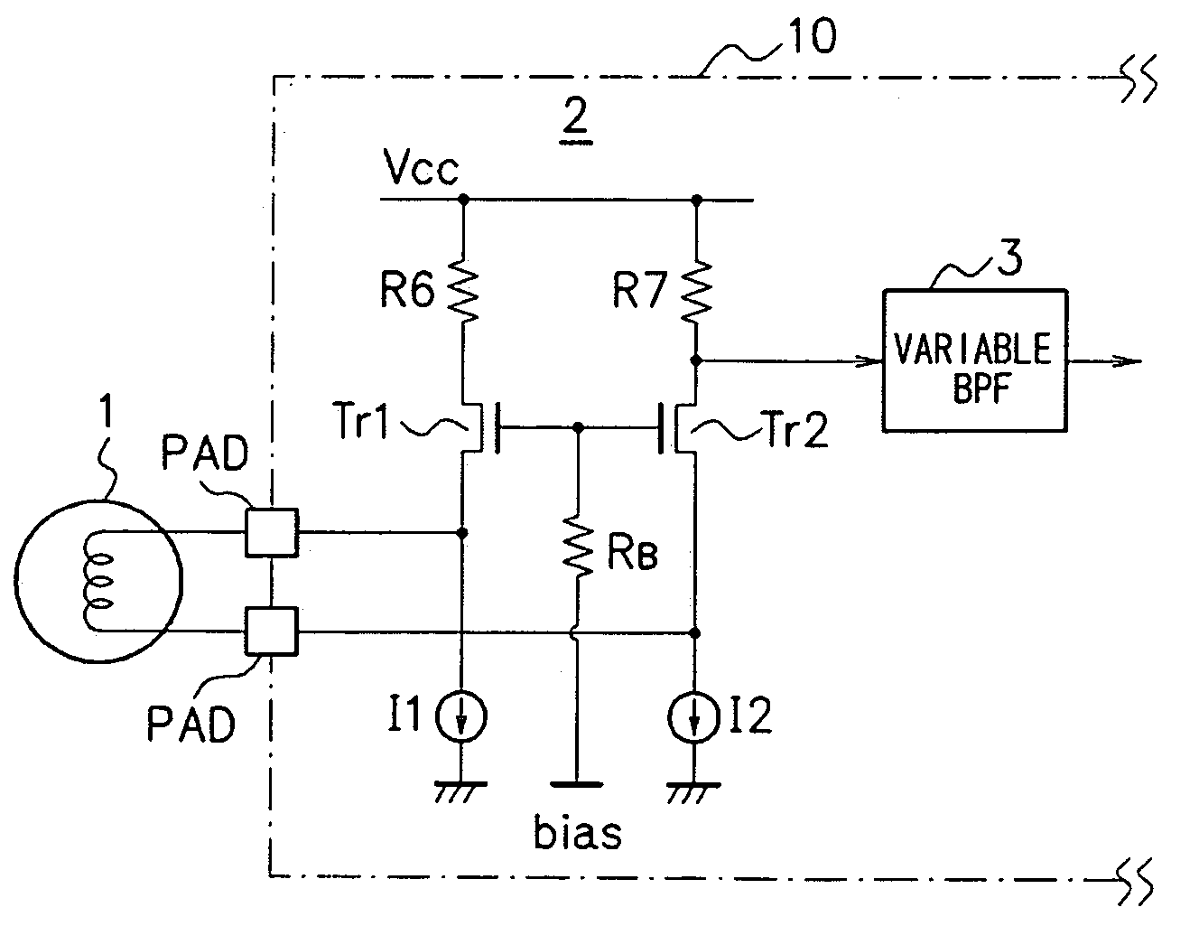
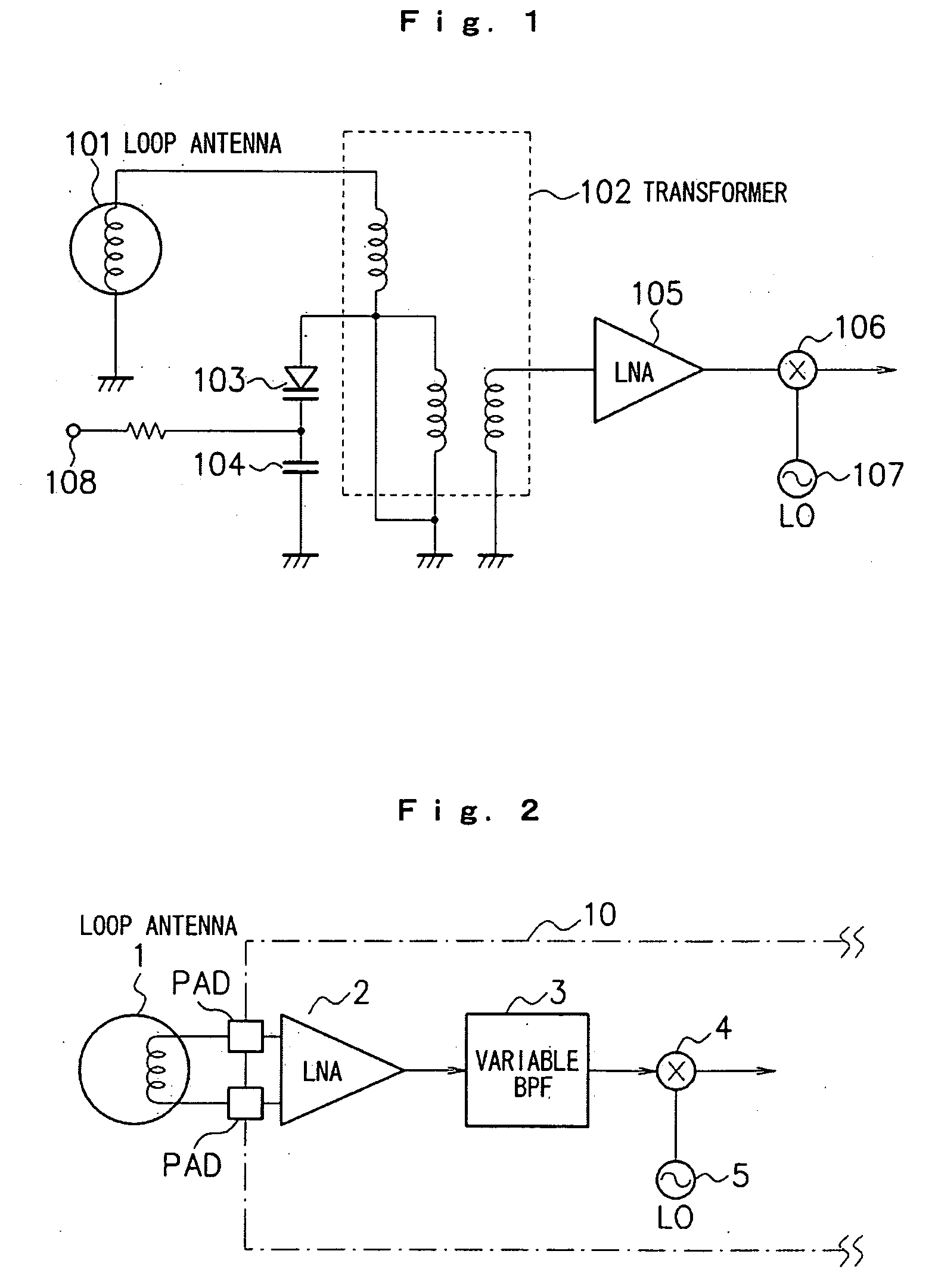
[0021]Embodiments of the present invention will be described below with reference to the drawings. FIG. 1 is a view illustrating an exemplary configuration of the main part of a broadcast signal receiving apparatus according to the present embodiment. As described in FIG. 1, the broadcast signal receiving apparatus according to the present embodiment includes a loop antenna 1, LNA (low noise amplifier) 2 directly connected to the loop antenna 1, variable BPF 3, mixer 4 and local oscillator 5. Of these components, the LNA 2, variable BPF 3, mixer 4 and local oscillator 5 are integrated in a single IC chip 10 by means of a process such as CMOS (Complementary Metal Oxide Semiconductor) or Bi-CMOS (Bipolar-CMOS).

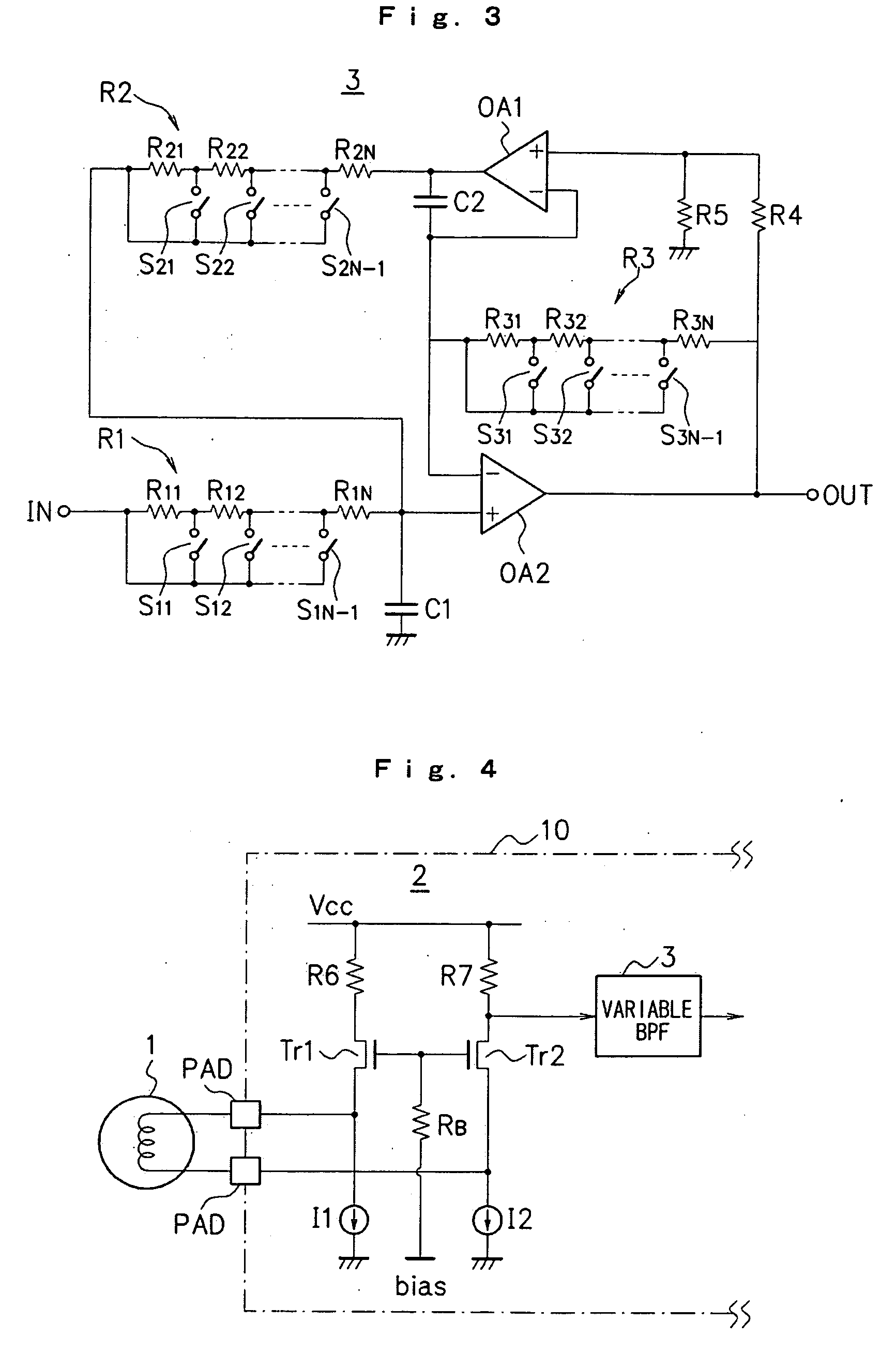
[0022]The variable BPF 3 is connected in a stage following the LNA 2, and the passed frequency band thereof is adapted to be variable. According to the present embodiment, the variable BPF 3 is an active filter for which the passed frequency band can be controlled by a resistanc...


PUM


Abstract

An LNA (2) is directly connected to a loop antenna (1), and a variable BPF (3), the passed frequency band of which is adapted to be variable, is connected in a stage following the LNA (2). In this way, the variable BPF (3) is used to configure a variable tuning circuit exhibiting a high Q-value without using any impedance conversion transformer between the loop antenna (1) and the LNA (2), whereby almost all of the constituent elements of the tuner part can be integrated in an IC chip (10) and further the variable tuning can maintain an excellent selectivity of a target frequency.

Description

TECHNICAL FIELD[0001]The present invention relates to a broadcast signal receiving apparatus, and more particularly to an apparatus that receives a broadcast signal using a loop antenna.BACKGROUND ART[0002]Examples of antennas used in broadcast signal receiving apparatuses such as a radio receiver include bar antennas and loop antennas. Bar antennas can be miniaturized irrespective of the wavelength of received radio wave, so they are in widespread use for the reception of long wave and medium wave, for example, in an AM radio or wave clock. Since the resonance impedance of bar antenna is large (several hundred KQ), it is combined with a variable-capacitance device to configure a tuning circuit.[0003]Loop antennas are based on the principle that extracts induced electromotive force dependent on the variation in magnetic field in the inner side of a coil formed by turning a conductive wire several times, and are usually connected with a capacitor to be used as a resonance circuit. Fo...

Claims


Application Information

Patent Timeline
Patent Type & Authority Applications(United States)
IPC IPC(8): H04B1/16
CPCH03H11/1252H03H11/1291H03J3/185H04B1/18
Inventor IKEDA, TAKESHIMIYAGI, HIROSHI
Owner NEURO SOLUTION CORP
Why Eureka
Try Eureka