Composite piezoelectric material, ultrasonic probe, ultrasonic endoscope, and ultrasonic diagnostic apparatus

a piezoelectric material and ultrasonic probe technology, applied in diagnostics, mechanical vibration separation, medical science, etc., can solve the problems of poor radiation efficiency, large amount of energy turns into heat, and the temperature rise of ultrasonic probes, so as to reduce the peak temperature of the vibrator array used for transmitting or receiving ultrasonic waves in ultrasonic imaging, the effect of increasing the thermal conductivity coefficien

Inactive Publication Date: 2008-12-18
FUJIFILM CORP
View PDF8 Cites 68 Cited by
  • Summary
  • Abstract
  • Description
  • Claims
  • Application Information

AI Technical Summary

Benefits of technology

[0022]According to the present invention, since the anisotropic heat conducting material having a higher coefficient of thermal conductivity in at least one direction is provided between the plural piezoelectric materials, the heat generated in the piezoelectric vibrator can be rapidly transferred to the outside in the at least one direction. Therefore, the peak temperature of the vibrator array to be used for transmitting or receiving ultrasonic waves in ultrasonic imaging can be reduced.

Problems solved by technology

Not the whole energy of the drive signals is converted into acoustic energy, and the considerable amount of energy turns into heat.
Thus, there has been a problem of temperature rise of the ultrasonic probe during its use.
However, in Documents 1-3, the radiation efficiency is poor because the heat generated in the vibrator is released only through the interface between the vibrator and the backing material.
That is, the piezoelectric ceramics such as PZT forming the vibrator is poor in heat conductivity, and the epoxy resin, silicone resin, urethane resin, or the like filling between plural vibrators are also poor in heat conductivity, and therefore, sufficient radiation is not expected.
Accordingly, there has been a problem that radiation at the central part of the vibrator array becomes especially insufficient and causes a temperature distribution in which the temperature at the central part is higher than that of the other part, and the peak temperature becomes higher.
Further, in Document 4, at least one acoustic matching layer is made as an acoustic matching layer with low heat conductivity, however, the temperature rise of the vibrator cannot be avoided unless the heat generated in the vibrator is efficiently transferred to the outside.

Method used


Image

  • Composite piezoelectric material, ultrasonic probe, ultrasonic endoscope, and ultrasonic diagnostic apparatus
  • Composite piezoelectric material, ultrasonic probe, ultrasonic endoscope, and ultrasonic diagnostic apparatus
  • Composite piezoelectric material, ultrasonic probe, ultrasonic endoscope, and ultrasonic diagnostic apparatus

Examples


first embodiment

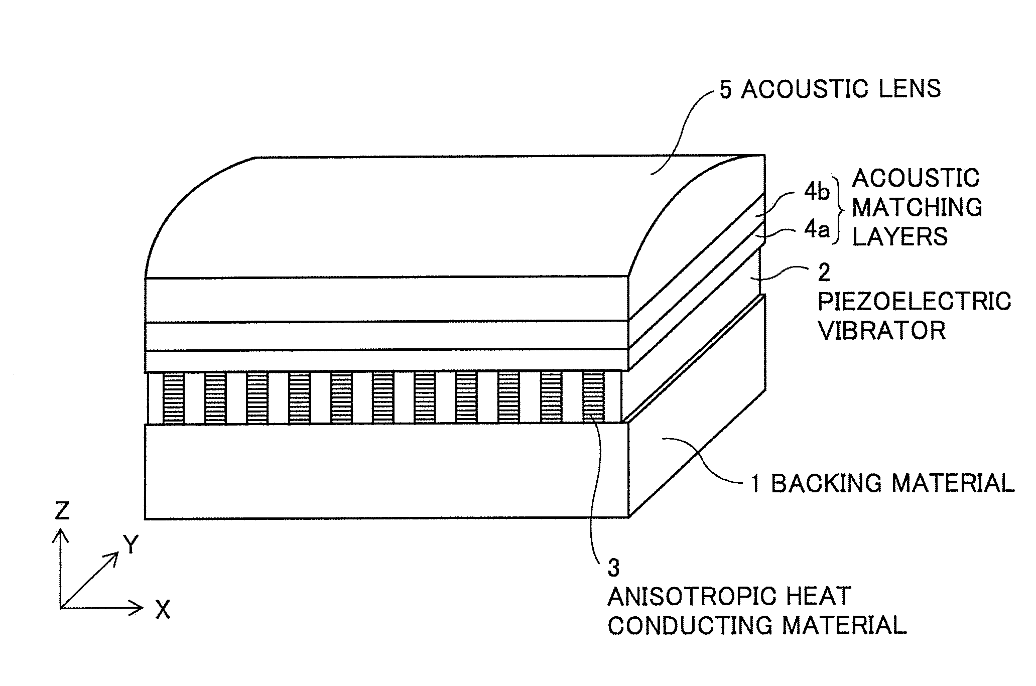
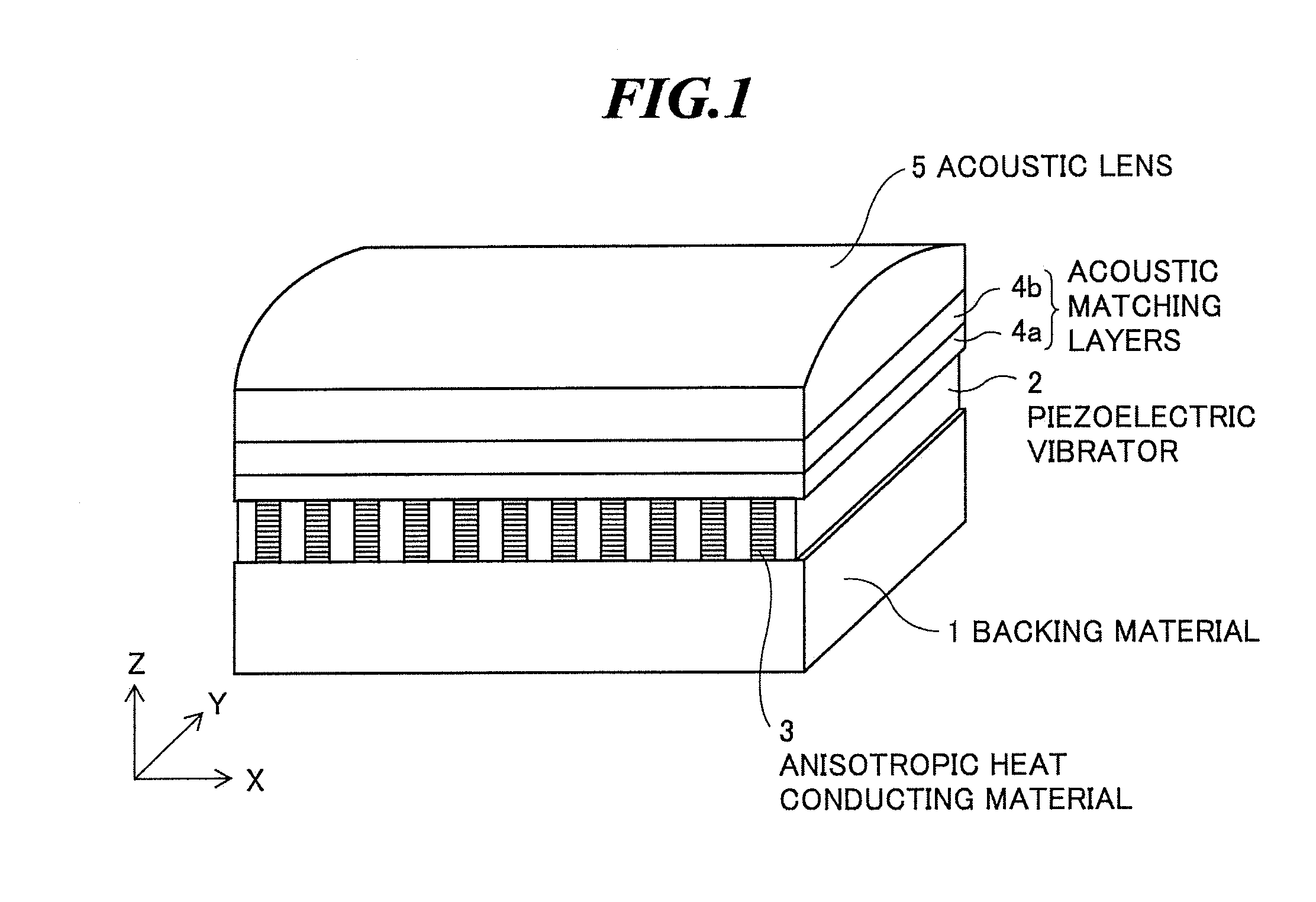
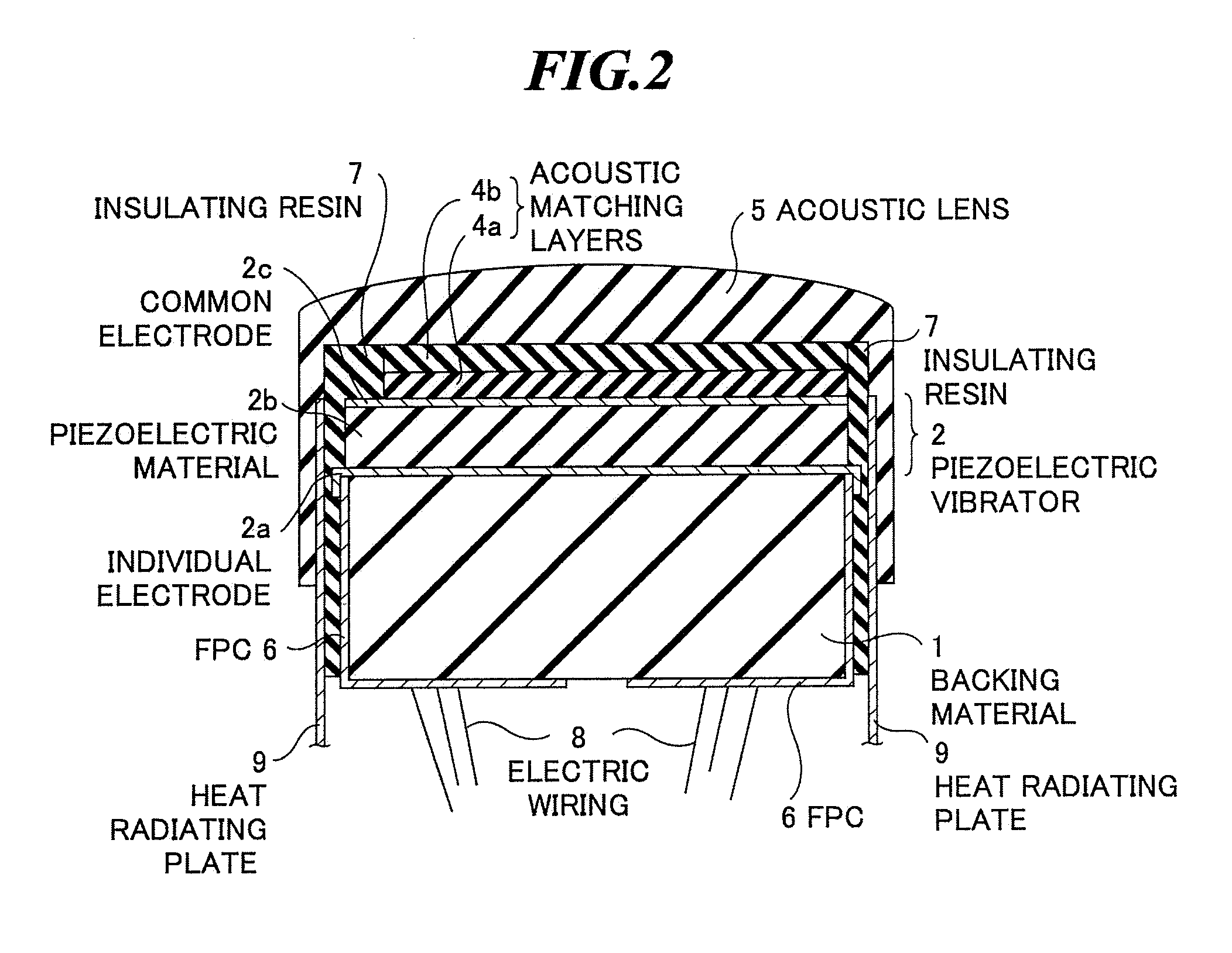
[0045]FIG. 1 is a perspective view schematically showing an internal structure of an ultrasonic probe according to the present invention, and FIG. 2 is a sectional view of the internal structure of the ultrasonic probe shown in FIG. 1 along a plane in parallel with the YZ-plane. The ultrasonic probe is used when extracavitary scan is performed in contact with an object to be inspected or when intracavitary scan is performed by being inserted into a body cavity of the object.

[0046]As shown in FIGS. 1 and 2, the ultrasonic probe has a backing material 1, plural ultrasonic transducers (piezoelectric vibrators) 2 arranged on the backing material 1, an anisotropic heat conducting material 3 provided between those piezoelectric vibrators 2, one or plural acoustic matching layers (two acoustic matching layers 4a and 4b are shown in FIGS. 1 and 2) provided on the piezoelectric vibrators 2, an acoustic lens 5 provided on the acoustic matching layers according to need, two flexible printed ci...

second embodiment

[0072]As shown in FIGS. 7A and 7B, in the composite piezoelectric material used in the present invention, the carbon fibers as the heat conducting members 3a are arranged substantially in parallel to the longitudinal direction of the piezoelectric materials 2b (the Y-axis direction). Thereby, the temperature distribution in the vibrator array is flattened. The longitudinal direction of the heat conducting members 3a may not be necessary to be in parallel to the Y-axis direction, but it is desirable that the angle formed by the heat conducting member 3a and the Y-axis direction is 30° or less for flattening the temperature distribution of the vibrator array.

[0073]The diameter of each carbon fiber is about 10 μm. The resins 3b are formed by pouring the epoxy resin into spaces between the plural fibers and curing it. The volume fraction of carbon fibers in the anisotropic heat conducting material 3 is preferably from 20% to 78%, and 50% in the embodiment. In the second embodiment, espe...

third embodiment

[0079]The coefficient of thermal conductivity of carbon fiber is about 800 W / (m·K), and the coefficient of thermal conductivity of epoxy resin is about 0.2 W / (m·K). Therefore, the coefficient of thermal conductivity of the anisotropic heat conducting material 3 is about 320 W / (m·K) with respect to the longitudinal direction of the carbon fiber and about 0.33 W / (m·K) with respect to the direction perpendicular to the longitudinal direction of the carbon fiber, and they are greatly improved compared to about 0.2 W / (m·K) in the conventional case of the epoxy resin only. In the third embodiment, the coefficients of thermal conductivity are remarkably improved in both X-axis direction and Y-axis direction.

[0080]Next, a modified example of the third embodiment of the present invention will be explained. In the modified example, the piezoelectric vibrator has a multilayered structure as is in the case shown in FIG. 5, and the rest of the configuration is the same as that in the third embod...


PUM

PropertyMeasurementUnit
surface temperatureaaaaaaaaaa

Abstract

A composite piezoelectric material capable of reducing a peak temperature of a vibrator array to be used for transmitting or receiving ultrasonic waves in ultrasonic imaging. The composite piezoelectric material includes: plural piezoelectric materials arranged along a flat surface or curved surface; and an anisotropic heat conducting material having a higher coefficient of thermal conductivity in at least one direction and provided between the plural piezoelectric materials and / or at outer peripheries of the plural piezoelectric materials.

Description

BACKGROUND OF THE INVENTION[0001]1. Field of the Invention[0002]The present invention relates to a composite piezoelectric material to be used in an ultrasonic transducer array for transmitting or receiving ultrasonic waves.[0003]Further, the present invention relates to an ultrasonic probe including such an ultrasonic transducer array and to be used when intracavitary scan or extracavitary scan is performed on an object to be inspected, and an ultrasonic endoscope to be used by being inserted into a body cavity of the object. Furthermore, the present invention relates to an ultrasonic diagnostic apparatus including such an ultrasonic probe or ultrasonic endoscope and a main body apparatus.[0004]2. Description of a Related Art[0005]In medical fields, various imaging technologies have been developed in order to observe the interior of an object to be inspected and make diagnoses. Especially, ultrasonic imaging for acquiring interior information of the object by transmitting and recei...

Claims


Application Information

Patent Timeline
Patent Type & Authority Applications(United States)
IPC IPC(8): A61B8/00
CPCB06B1/0622G10K11/004H10N30/852
Inventor HYUGA, HIROAKI
Owner FUJIFILM CORP
Why Eureka
Try Eureka