Control system using pulse density modulation

a control system and pulse density technology, applied in the direction of electric control, machine/engine, valve operating means/release devices, etc., can solve the problems of reducing the usable control range, reducing the resolution of control of the actuator, and the usable range of flow for a given application can be very small in comparison to the full flow capability, so as to achieve more accurate control of the actuator and higher resolution

Inactive Publication Date: 2008-12-25
DELPHI TECH INC
View PDF12 Cites 19 Cited by
  • Summary
  • Abstract
  • Description
  • Claims
  • Application Information

AI Technical Summary

Benefits of technology

[0005]Briefly described, a method for modified pulsed control of an electromechanical actuator in accordance with the invention comprises the steps of a) setting a common time length for all of the pulses in a pulse train, and b) varying (modulating) the number of such pulses per unit time (repetition rate) by varying the length of time between pulses in the train. Such control is defined herein as pulse-density modulation, or PDM. Especially in applications having a relatively low duty cycle if controlled by the prior art Pulse Width Modulation (PWM), PDM control results in more accurate control of an actuator, with higher resolution. The method is especially useful in controlling flow of a fluid, either liquid or gas, through a valve, and especially at relatively low flow rates at high supply pressures.

Problems solved by technology

As the pressure drop across the valve is increased, the relationship of duty cycle to flow remains linear, but the slope increases, resulting in a reduced usable control range with increasing pressure.
This limitation can reduce the resolution of control of the actuator.
Also, the usable range of flow for a given application can be very small in comparison to the full flow capability of the valve.
In this situation, for example, a variation of only a few percent in the duty cycle may encompass the entire range of usable flow, leading to poor actuator position resolution and poor control of flow.

Method used


Image

  • Control system using pulse density modulation
  • Control system using pulse density modulation
  • Control system using pulse density modulation

Examples


Embodiment Construction

[0015]The present invention in PDM methodology is applicable to control of any electromechanical actuator controllable by PWM control methodology in accordance with the prior art, and is directly replaceable of such PWM control. Such actuators may include but are not limited to linear actuators and rotary actuators. Some typical valve applications are engine throttle valves, engine exhaust gas recirculation valves, and fuel flow control valves for engines and for hydrocarbon fuel reformers. Also, of particular interest, because of the flow accuracy demanded in its application, the PDM methodology is specially suited for use in fuel injectors.

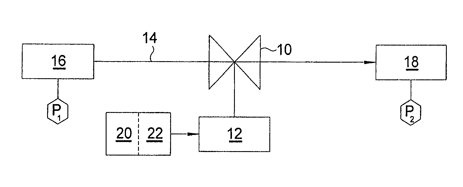
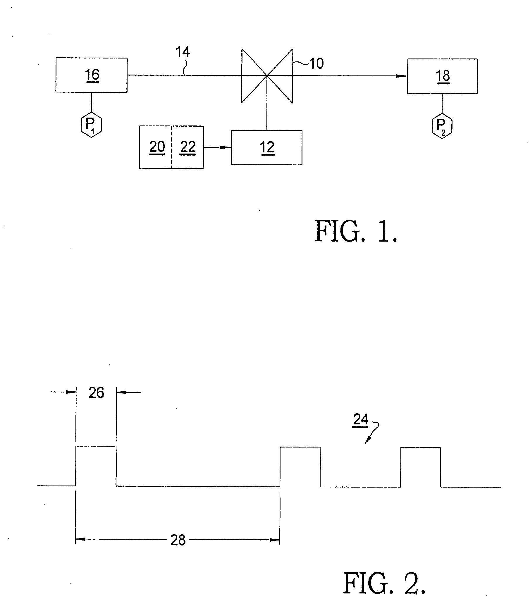
[0016]FIG. 1 shows a schematic valve 10 operated by an actuator 12 for controlling flow rate of a fluid 14 through valve 10 from a source 16 at pressure P1 to a destination 18 at pressure P2, the difference P1−P2 (ΔP) representing the pressure drop across valve 10. Actuator 12 is controlled by an electronic controller 20 and driver 22. Control m...


PUM


Abstract

A method for modified pulsed control of an electromechanical actuator in accordance with the invention comprising the steps of a) setting a common time length for all of the pulses in a pulse train, and b) varying (modulating) the number of such pulses per unit time (repetition rate) by varying the length of time between pulses in the train. Such control is defined herein as pulse-density modulation, or PDM. Especially in applications having a relatively low percent duty cycle if controlled by the prior art Pulse Width Modulation (PWM), PDM control results in more accurate control of an actuator, with higher resolution. The method is especially useful in controlling flow of a fluid, through a valve, such as a fuel injector, and especially at relatively low flow rates at high supply pressures P1 in the fluid supply.

Description

TECHNICAL FIELD[0001]The present invention relates to electronic systems for control of electromechanical actuators; more particularly, to pulsed electronic control systems; and most particularly, to an electronic control system employing a fixed width pulse applied at a variable frequency, resulting in modulation of pulse density per unit time.BACKGROUND OF THE INVENTION[0002]In the art of electronic control of electromechanical actuators such as valve actuators, it is well known to apply a pulsed electronic signal to the actuator over a percent of unit time (percent duty cycle). Because the time-width of each pulse may be varied between 0% and 100% duty cycle, this approach is known in the art as control by Pulse Width Modulation. In this way, there is a linear relationship between duty cycle and flow of a fluid material through a valve, given a fixed supply pressure to the valve and a fixed pressure drop across the valve. The time-average flow rate of fluid through the valve is p...

Claims


Application Information

Patent Timeline
Patent Type & Authority Applications(United States)
IPC IPC(8): F02M51/00F16K31/02
CPCF02D41/20F02M45/02F02M51/061
Inventor GOULETTE, DAVID A.LECEA, OSCAR A.
Owner DELPHI TECH INC
Why Eureka
Try Eureka