Sheet finisher, image forming apparatus using the same, and sheet finishing method

Active Publication Date: 2008-12-25
KK TOSHIBA +1
View PDF5 Cites 24 Cited by
  • Summary
  • Abstract
  • Description
  • Claims
  • Application Information

AI Technical Summary

Benefits of technology

[0013]The present invention has been made in view of the above circumstances, and it is an object to provide a sheet finisher which performs a saddle-stitching and folding process and can reduce the damage received by the surface of a reinforc

Problems solved by technology

However, the time in which the folded part of the sheet bundle is pressed by the nip of the fold rollers is short, and the whole folded part is simultaneously pressed by the nip of the fold rollers, and accordingly, the pressure is dispersed to the whole fold line.
Particularly, in the case where the number of sheets is large, or in the case where a thick sheet is contained in the sheet

Method used


Image

  • Sheet finisher, image forming apparatus using the same, and sheet finishing method
  • Sheet finisher, image forming apparatus using the same, and sheet finishing method
  • Sheet finisher, image forming apparatus using the same, and sheet finishing method

Examples


Example

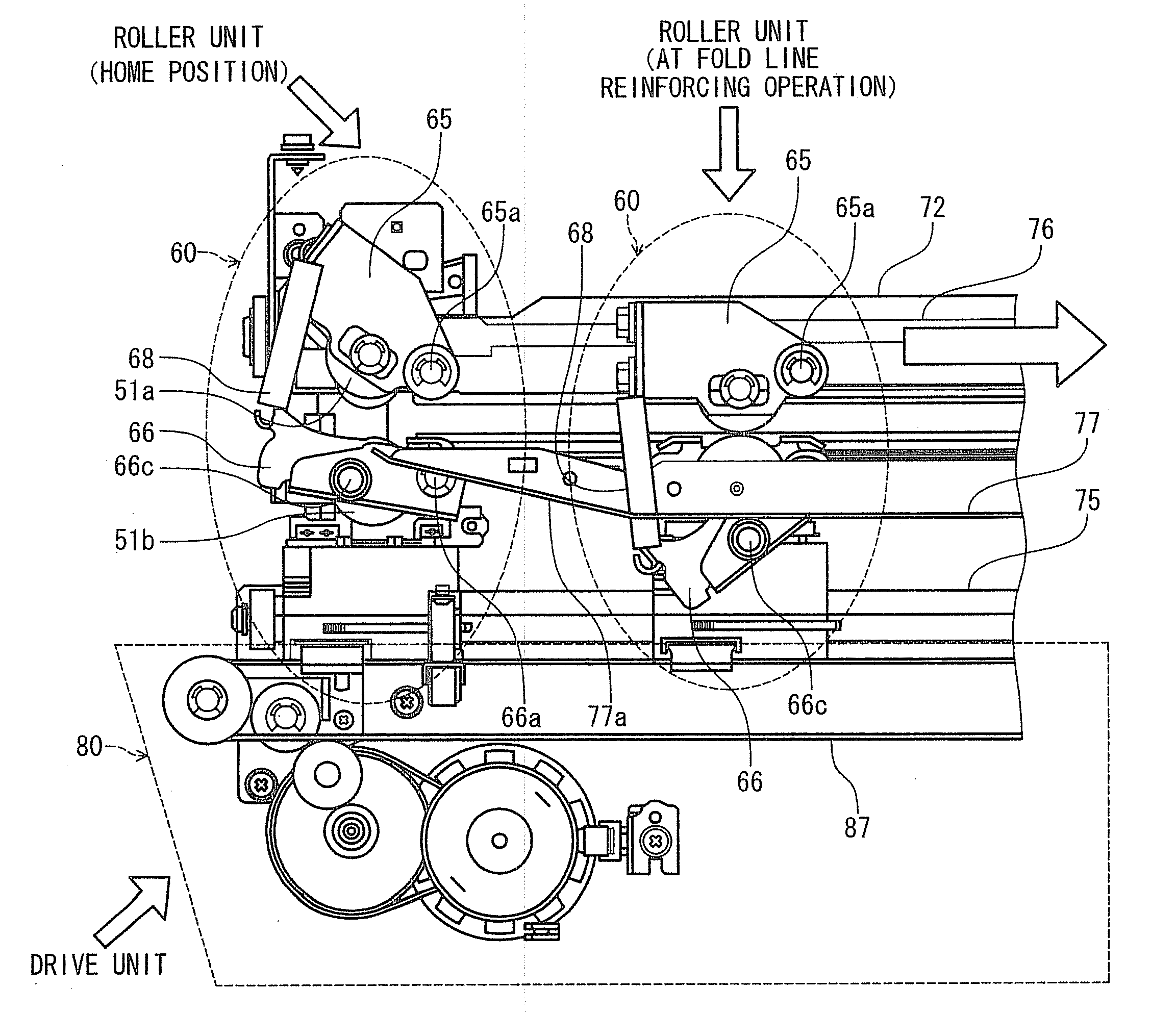
[0194]Similarly to the first embodiment, the sheet bundle is pressed into the nip of a fold roller pair 38 by a fold blade 37, and a fold line is formed. Thereafter, the fold line of the sheet bundle is transported to substantially the center of the reinforce roller 113 by the rotation of the fold roller pair 38 and is stopped.

[0195]Thereafter, the roller unit 110 is moved in the fold line direction. Although the reinforce roller 113 starts to move while rotating on the upper guide 121, when passing through the placement table support section 122a, the fold roller descends by the elasticity of the compression spring 112, bends the upper guide 121 downward, and presses the sheet bundle by the elastic force of the compression spring 112 (see FIG. 21C). Although an upward elastic force to return to the horizontal position is generated from the upper guide 121, the compression spring 112 is selected to have such elastic force that the downward pressing can be performed with a sufficient...

Example

[0200]In the third embodiment, the upper guide 121 formed of the elastic member such as rubber is not used. Thus, when the reinforce roller 113 climbs over the end of a sheet bundle 100A or 100B, there is a fear that the sheet bundle is turned up and the sheet bundle is damaged.

[0201]Then, in the fold reinforcing unit 50b of the third embodiment, a groove-like edge clearance 130a or 130b is provided in the placement table 130 at a position corresponding to the end of the sheet bundle 100A or 100B.

[0202]The edge clearance 130a is for the sheet bundle 100A of a large size (see FIGS. 22A and 22B), and the edge clearance 130b is for the sheet bundle 100B of a small size (see FIGS. 22C and 22D).

[0203]When the reinforce roller 113 starts to move from the home position, and reaches the end of the sheet bundle 100A or 100B, by the effect of the recess shape of the edge clearance 130a or 130b, the end of the sheet bundle 100A or 100B descends by the reinforce roller 113 (see FIG. 22B or FIG....


PUM

PropertyMeasurementUnit
Thicknessaaaaaaaaaa
Speedaaaaaaaaaa

Abstract

A sheet finisher of the invention includes a saddle stitch unit configured to stitch a center of a sheet bundle, in which printed sheets are bundled, with a staple, a fold unit configured to fold the center stitched by the saddle stitch unit and to form a fold line, and a fold reinforcing unit configured to reinforce the fold line formed by the fold unit, the fold reinforcing unit includes a roller unit that includes a reinforce roller and moves along a direction of the fold line while applying pressure by the reinforce roller to the fold line of the sheet bundle transported from the fold unit, a drive unit configured to move the roller unit along the direction of the fold line, and a control unit configured to control a movement speed of the roller unit, and the control unit causes the roller unit to move at a first speed in an outside of a specified range including the edge of the staple, and causes the roller unit to move at a second speed not higher than the first speed in the specified range including the edge of the staple.

Description

BACKGROUND OF THE INVENTION[0001]1. Field of the Invention[0002]The present invention relates to a sheet finisher, an image forming apparatus using the same, and a sheet finishing method, particularly to a sheet finisher to perform a folding process of a printed sheet, an image forming apparatus using the same, and a sheet finishing method.[0003]2. Description of the Related Art[0004]Hitherto, there is known a sheet finisher which is placed downstream of an image forming apparatus, such as a copier, a printer or an MFP (Multi-Function Peripheral), and performs a post-processing, such as a punching process or a stitching process, on a printed sheet.[0005]Recently, the function of this sheet finisher is diversified, and a sheet finisher is proposed which has, in addition to the function of the punching process and the stitching process, the function of a folding process to fold a part of a sheet, and the function of a saddle-stitching and folding process to staple the center of a shee...

Claims


Application Information

Patent Timeline
IPC IPC(8): B41F13/56B41L43/00B65H45/16B31B50/56
CPCB65H37/04B65H45/18B65H2301/51232B65H2701/13212B65H2801/27G03G15/6582G03G2215/00831G03G2215/00877
Inventor IGUCHI, KENSASAHARA, KATSUYAKAWAGUCHI, TAKAHIROTAGUCHI, HIROYUKITSUCHIYA, KATSUHIKO
Owner KK TOSHIBA
Why Eureka
Try Eureka