
Control and Power Device for a Rotating Electrical Machine

a technology of electrical machines and control devices, which is applied in the direction of electronic commutators, motors/generators/converter stoppers, dynamo-electric converter control, etc., can solve the problem of the size of the electronic control and power modules

Active Publication Date: 2008-12-25
VALEO EQUIP ELECTRIC MOTEUR
View PDF14 Cites 3 Cited by
  • Summary
  • Abstract
  • Description
  • Claims
  • Application Information

AI Technical Summary

Benefits of technology

The present invention proposes a control and power device for a rotary electrical machine that can be incorporated within the casing of an alternator starter. The device includes a management circuit and a power circuit with multiple power transistors and control circuits. The control circuits are connected to the management circuit through a unique connecting means that applies a voltage and transmits at least one potential. This reduces the number of connections and physical size of the device. The control circuits are activated by the potential which supplies power to the grids of the transistors. The device also includes means for detecting breakage of the connecting means and a comparator with hysteresis for stabilizing the comparison. The technical effects of the invention are a smaller size of the control and power device and improved efficiency in incorporating it into the alternator starter.

Problems solved by technology

However, because of the increasingly severe restrictions of miniaturisation, and manufacturing constraints, in particular as regards the dimensions of the said casing that have to be followed, the size of the electronic control and power module is a problem due to the numerous components which are necessary in the said module, and due also to the interconnections by which these various components are connected together.

Method used


Image

  • Control and Power Device for a Rotating Electrical Machine
  • Control and Power Device for a Rotating Electrical Machine
  • Control and Power Device for a Rotating Electrical Machine

Examples


Embodiment Construction

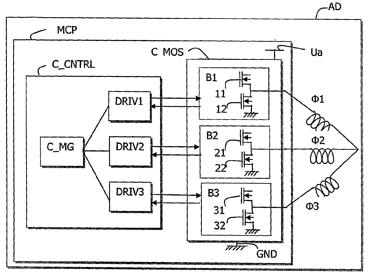
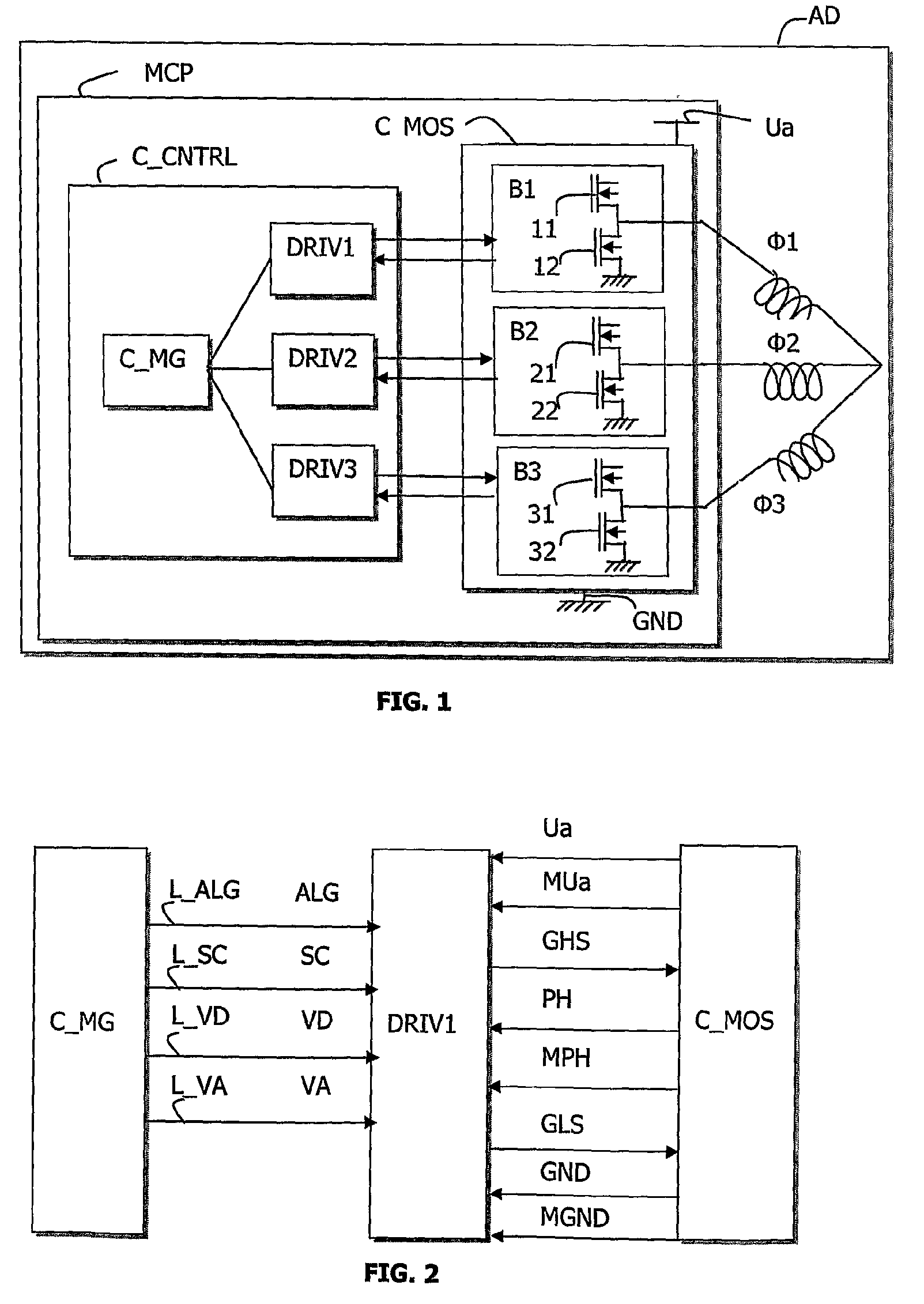
[0038]FIG. 1 shows a module, or control and power device MCP according to the invention for a starter alternator AD of a vehicle.

[0039]The control and power module MCP comprises:[0040]a power circuit or unit C_MOS which includes a rectifier bridge, the said bridge having three identical branches B1, B2 and B3,[0041]a control unit C_CNTRL which includes control circuits DRIV1, DRIV2 and DRIV3, also referred to as drivers, and a management circuit C_MG.

[0042]The alternator starter AD is, in the example given, a three-phase machine which has three phases φ1, φ2 and φ3, each of which is connected to one of the respective branches B1, B2 and B3 of the power unit C_MOS. Because the three branches B1, B2 and B3 are identical to each other, only the first branch B1 will be described in the rest of this description.

[0043]The first branch B1 of the rectifier bridge has two interruptors11 and 12 which are power transistors. The first transistor 11 is called the high side transistor. It is conn...


PUM


Abstract

A control and power device for a rotating electrical machine comprising a management circuit and a power circuit including a number of power transistors and driver circuits associated with the power transistors. The invention is characterized in that it comprises connection means between the management circuit and the driver circuits for switching on the driver circuits and transmitting at least one transit potential between the management circuit and the driver circuits. The invention is applicable to alternator-starter.

Description

FIELD OF THE INVENTION[0001]This invention relates to a control and power device for a rotary electrical machine, comprising a control circuit and a power circuit, the said power circuit including a plurality of power transistors and control circuits associated with the said transistors. The invention finds applications in the field of the automotive industry, and in particular in the field of alternators and alternator starters.CURRENT STATE OF THE ART[0002]In a motor vehicle having a heat engine and an alternator, both included in one casing, the said alternator comprises the following:[0003]a rotor, which represents an inductor or inductance, which is conventionally associated with two slip rings, and two brushes by which an excitation current is applied; and[0004]a multi-phase stator carrying a plurality of coils or windings, representing an armature, which are either star connected or delta connected in the most frequent case of a three-phase structure, and which deliver electr...

Claims


Application Information

Patent Timeline
Patent Type & Authority Applications(United States)
IPC IPC(8): H02P6/14
CPCH02K11/048H02P1/02H02P9/08H02P2101/45H02P9/26H02M7/00
Inventor PIERRET, JEAN-MARIEPICHON, FRANCIS
Owner VALEO EQUIP ELECTRIC MOTEUR
Learn More