Optical fiber, light amplifier and light source

a technology of optical fiber and light amplifier, which is applied in the direction of optical waveguide light guide, glass optical fibre, instruments, etc., can solve the problems of burnout of optical fiber coating material, earlier deterioration of coating material, and more problems, and achieve the effect of stable propagation of high-power ligh

Inactive Publication Date: 2008-12-25
FURUKAWA ELECTRIC CO LTD
View PDF7 Cites 3 Cited by
  • Summary
  • Abstract
  • Description
  • Claims
  • Application Information

AI Technical Summary

Benefits of technology

[0018]In order to solve the above-mentioned problem the inventors of the present invention insistently studied. As a result of this study, the inventors have found an optical fiber which is not damaged even if the optical fiber is bent with a small bending diameter by using a coating material that hardly absorbs leaked light, thereby allowing stable propagation of high-power light.
[0019]In this embodiment, since a transparent UV curable resin is used as a coating material, even if the optical fiber is bent with a diameter of about 10 mm at the minimum, it is possible to prevent deterioration of the coating material of the optical fiber due to absorption of leaked light and also prevent breakage of the optical fiber.
[0023]Accordingly, with the above-described embodiments, a part of the colored layer over the secondary coating layer is removed and the leaked light is lead into the outside of the coated optical fiber, which makes it possible to provide a highly-reliable transmission system without causing any problem even if the bending diameter becomes small in a coated optical fiber for guiding high-power light of 500 W or more.

Problems solved by technology

Under high-power transmission light conditions, there are more problems caused.
The first problem is that of burnout of a coating material of the optical fiber.
However, when an optical fiber is bent with a small bending diameter, light transmitted is leaked from the core, through the clad, coating materials to the outside of the optical fiber.
Then, as described above, as the power of propagated light becomes higher, there may occur a problem that has not occurred for the conventional light intensity.
This may result in earlier deterioration of the coating material than that used in the conventional way and easy breakage of the optical fiber.
The second problem associated with high output of optical power regards fiber fuse.
Besides, fiber fuse occurs only when a particular condition is met, and the possibility of occurrence of fiber fuse is extremely low.
However, once fiber fuse occurs, the fiber fuse propagates toward an optical amplifier or light source, which may break a part of the optical fiber or the whole length of the optical fiber.
Further, when fiber fuse reaches an optical component, or an optical device connected to the optical fiber, the optical component or optical device may be also broken, and the optical transmission path may be also broken.

Method used


Image

  • Optical fiber, light amplifier and light source
  • Optical fiber, light amplifier and light source
  • Optical fiber, light amplifier and light source

Examples


example 1

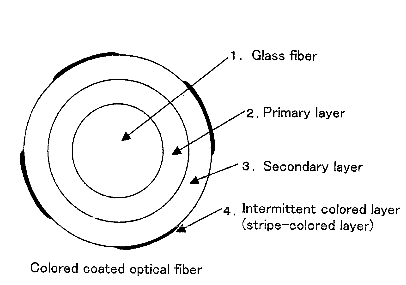
[0084]Color is applied in strips at three points on the outer surface of the optical, fiber in such a manner that the colored layer makes up approximately 50% of the outer surface area of the optical fiber and the colored layer portion alternates with the non-colored layer portion. Then, this color coated optical fiber is used as an example 1 (see FIGS. 14 and 15). For comparison, a cross section of a conventional optical fiber completely coated with a colored layer is shown in FIG. 13.

example 2

[0085]Color is applied in strips at three points on the outer surface of the optical fiber in such a manner that the colored layer makes up approximately 50% of the superficial area of the optical fiber and the colored layer portion alternates with the non-colored layer portion. Here, in order that the stripes become spiral, the optical fiber is twisted when being colored (see FIG. 16). The way of twisting is the same as the method of twisting used in drawing in an optical fiber for improvement of PMD characteristic, that is, the optical fiber is twisted at a position after passing through a UV lamp so that the optical fiber is colored in spiral strips.


PUM


Abstract

A coated optical fiber capable of transmitting high-power light, which is an optical fiber having an outer surface coated with a coating material, is characterized in that the coating material is made of a transparent UV curable resin so as to prevent the coating material from absorbing light leaked outside from the optical fiber to generate heat. Further, a light transmitting method is characterized in that a fiber fuse propagation threshold which is a minimal light output required for fiber fuse propagation is obtained and a transmitted light output is controlled so that the transmitted light output becomes smaller than the fiber fuse propagation threshold.

Description

BACKGROUND OF THE INVENTION[0001]1. Field of the Invention[0002]The present invention relates to an optical fiber, an optical amplifier including a Raman amplifier and a rare-earth doped fiber amplifier and a light source used in the optical communication system.[0003]2. Description of the Related Art[0004]Recently, in a field of optical communications, high-speed communication and WDM communication technique require large transmission capacity. Particularly, in the WDM communication technique, the need for a broadband optical amplifier is increased which allows batch amplification of wideband signal light. The broadband optical amplifier which meets the demand includes a Raman amplifier and a rare earth doped fiber amplifier. The Raman amplifier is configured to utilize a stimulated Raman scattering effect so as to amplify signal light. In order to cause the stimulated Raman scattering effect of the Raman amplifier efficiently, high-power pumping light is required.[0005]In addition...

Claims


Application Information

Patent Timeline
Patent Type & Authority Applications(United States)
IPC IPC(8): G02B6/02
CPCG02B6/4482G02B6/02395
Inventor SEO, KOJINISHIMURA, NAOYA
Owner FURUKAWA ELECTRIC CO LTD
Why Eureka
Try Eureka