Chemiluminescence analyzer

Inactive Publication Date: 2008-12-25
HITACHI LTD
View PDF0 Cites 16 Cited by
  • Summary
  • Abstract
  • Description
  • Claims
  • Application Information

AI Technical Summary

Benefits of technology

[0014]To be more specific, in a flow cell having a configuration in which a flow channel is formed between a plate having micro-chambers formed thereon and a transparent substrate (upper plate) arranged to face the plate, and a solution (reagent) containing a reactive substrate is supplied to the individual micro-chambers through this flow channel, a means for changing the distance between the transparent substrate and the plate is provided. The micro-chambers are each formed as a concave portion on the plate. When the plate and the transparent substrate which determine a flow channel are located sufficiently far apart from each other, a reagent can freely flow in the flow cell. Accordingly, a necessary reagent can be supplied to the individual micro-chambers, and an unwanted chemical substance can be discharged from the micro-chambers. On the other hand, by either making the distance between the plate and the transparent substrate sufficiently small or attaching them completely to each other, PPi and ATP which have been produced in elongation reaction can either hardly diffuse to the outside of the individual micro-chambers or not diffuse at all. In other words, by changing the distance between the plate and the transparent substrate which determine the thickness of the flow channel of the flow cell, it is possible to achieve both rapid supply of a reaction solution and discharge of an unwanted chemical substance, and prevention of substances produced in an elongation reaction from diffusing to the outside of the individual micro-chambers. In this case, enzymes, such as luciferase and PPDK, are required for the luminescence reaction. Such enzymes

Problems solved by technology

In this technique, there has been a problem that the accuracy of determination of sequences or detection of DNA is impaired when PPi or ATP, which is a product of the reaction in individual micro-chambers, gets into neighboring chambers (occurrence of crosstalk).
However, if such measures are taken, it is impossible to rapidly supply substances required for elongation of DNA and chemiluminescence into the inside of individual micro-chambers, and to remove excess reaction substrates.
In other words, there has been a problem that a DNA complementary strand synthesizing reaction cannot proceed uniformly, though the uniform reaction is critical for increasing the accuracy of DNA analysis.
If rapid supply of reactive substrates an

Method used


Image

  • Chemiluminescence analyzer
  • Chemiluminescence analyzer
  • Chemiluminescence analyzer

Examples


Example

EXAMPLE 1

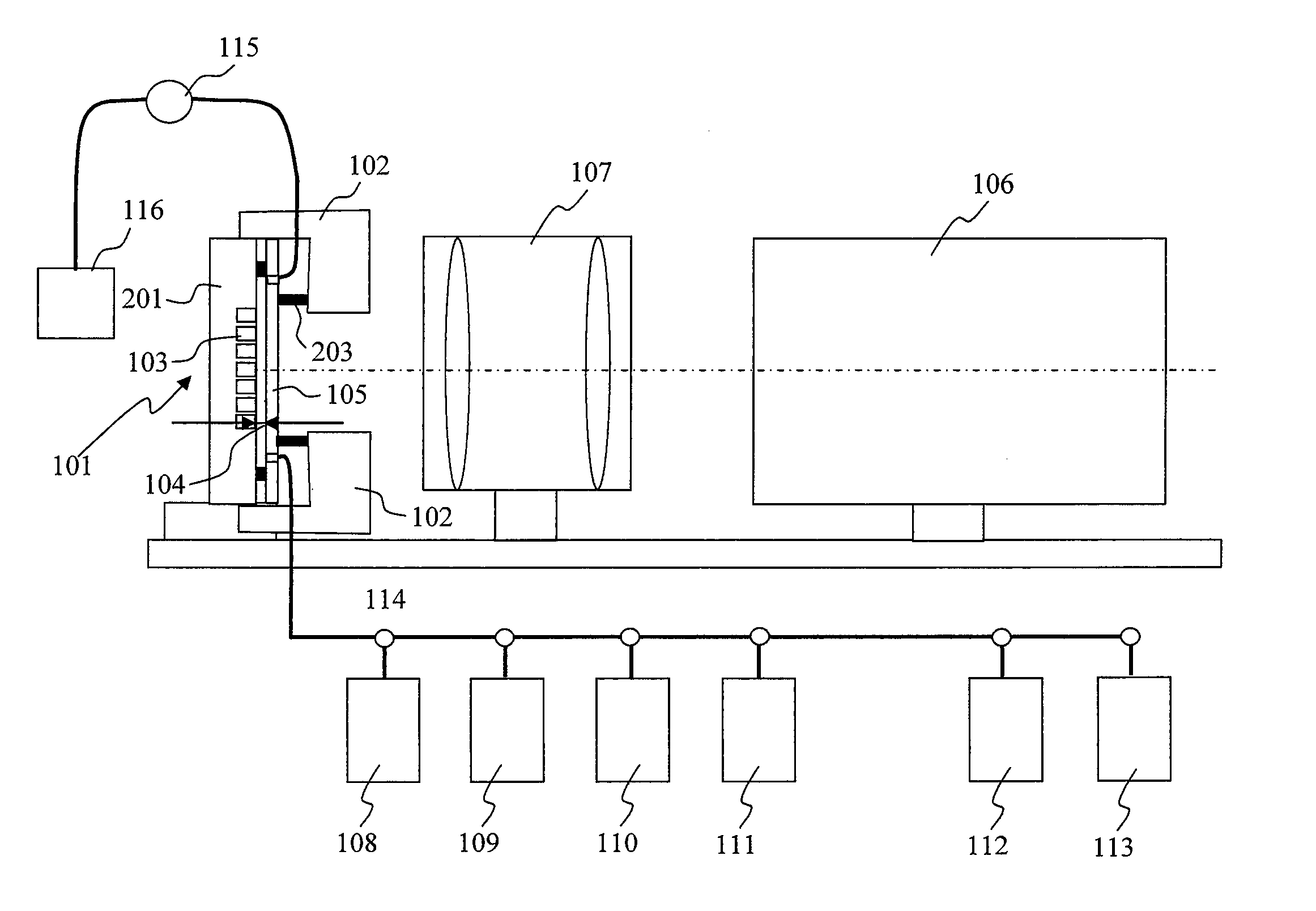
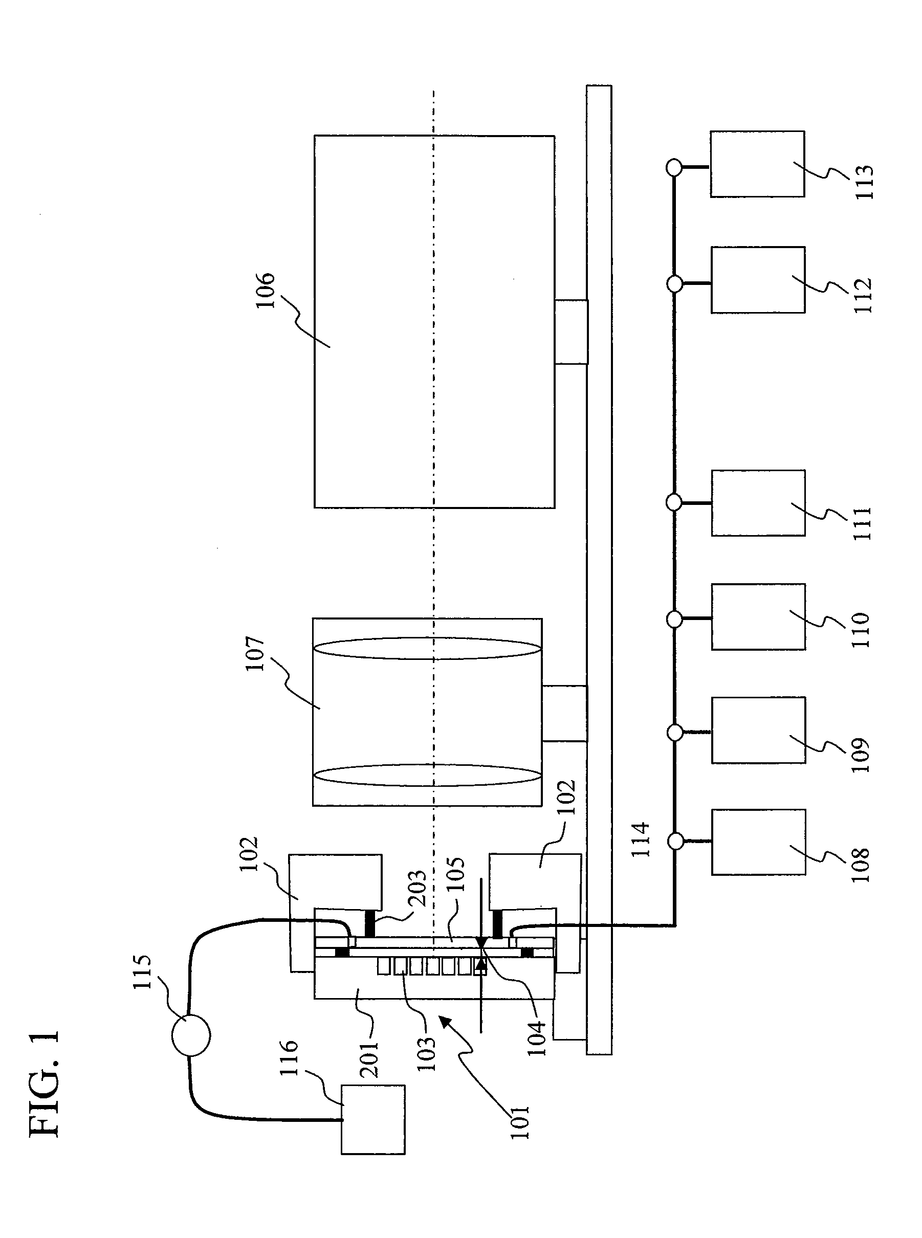
[0038]FIG. 1 is a drawing illustrating a configuration example of a chemiluminescence analyzer according to the present invention. In the chemiluminescence analyzer of the present example, various reagents flow through a flow cell 101 formed by a plate 201 having a large number of micro-chambers 103 formed thereon and a transparent substrate 105, and chemiluminescence from each of the large number of micro-chambers formed on the plate 201 is measured to determine a sequence. In the present invention, the thickness of a flow channel for reagents flowing therethrough is changed between the time of chemiluminescence measurement and the time of supply of reagents to the micro-chambers while a reagent is flowing through so that a conductance, a cross-sectional shape, and a cross-sectional area of the flow channel is changed. As a result, at the time of chemiluminescence measurement, while crosstalk among adjacent micro-chambers can be prevented, luminescence intensity can be im...

Example

EXAMPLE 2

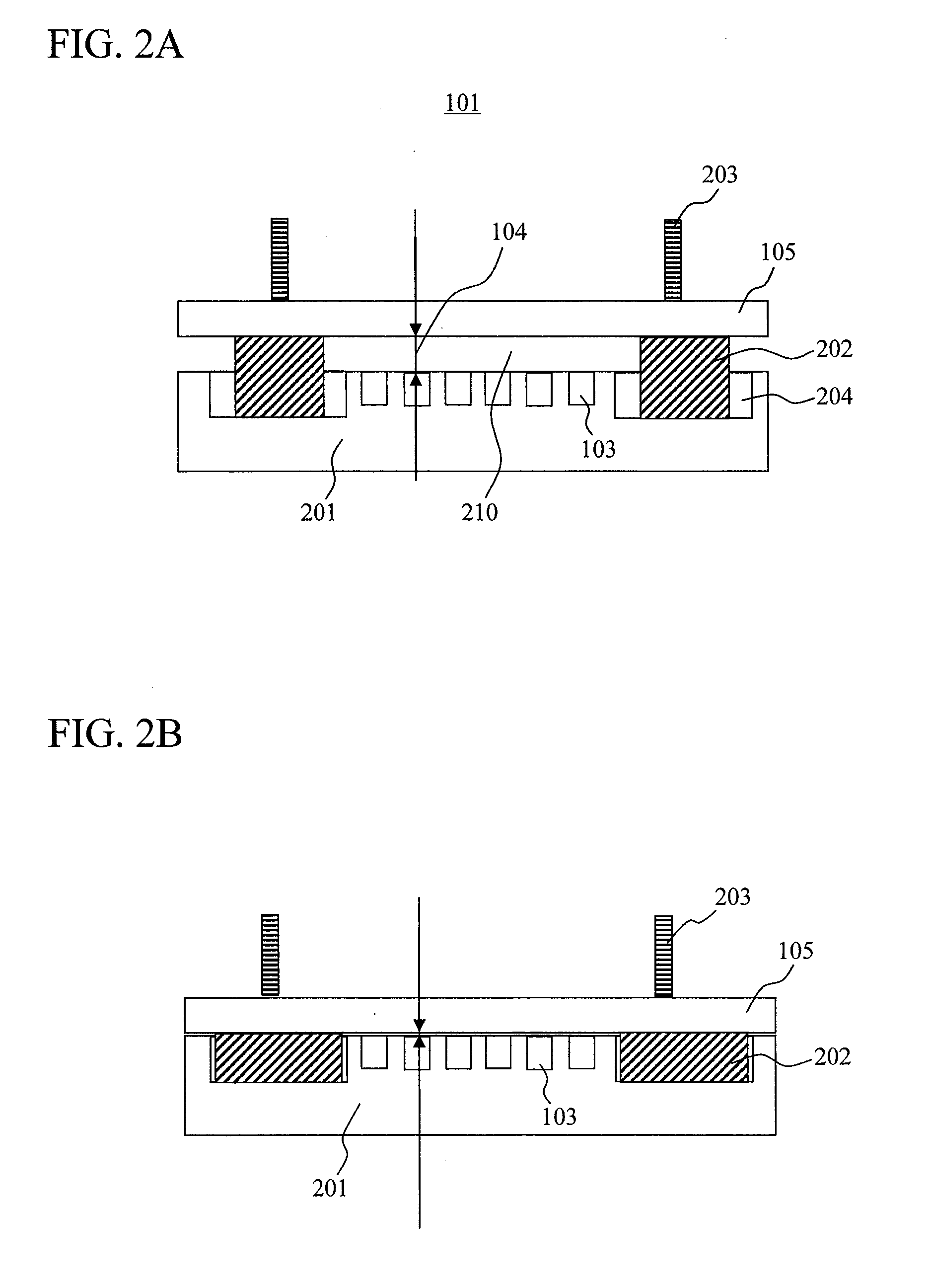
[0056]In Example 1, the flow channel thickness 104 was changed by causing elastic deformation of the spacers 202 so that diffusion of products from the micro-chambers 103 was inhibited. The present example is configured to achieve the same effect as in Example 1 by deforming a transparent substrate, serving as an upper plate of a flow cell, to change the thickness of the flow channel located immediately above the micro-chambers.

[0057]FIGS. 8A and 8B show schematic cross-sectional views of another example of the flow cell 101. In the flow cell 101 of the present example, it is configured that the flow channel thickness 104 can be reduced immediately above the micro-chambers 103 by bending the transparent substrate 701 with application of stress. FIG. 8A is a view illustrating a state when stress is not applied, while FIG. 8B is a view illustrating a state when stress is applied to reduce the flow channel thickness 104. In the present example, a part of the transparent subst...

Example

EXAMPLE 3

[0063]Instead of moving and deforming the transparent substrate and the plate 201, another transparent substrate is provided in the flow channel in the flow cell so as to prevent the diffusion of products from the micro-chambers 103. FIG. 11 shows a system configuration example of the chemiluminescence analyzer. In the place of the rods 203 and the driving section 102 in FIG. 1, electromagnets 1001 and a driving section 102 for supporting and driving the electromagnets 1001 are respectively provided.

[0064]FIG. 12A shows a schematic cross-sectional view of a state where the flow channel thickness of the flow cell has been increased, and FIG. 12B shows a schematic cross-sectional view of a state where the flow channel thickness has been reduced. In a configuration where a transparent substrate 1101 made of polypropylene is provided in the flow channel, and neodymium magnets 1102 (main components: neodymium, iron, and boron) are each covered on the surface with polypropylene ...


PUM


Abstract

The present invention aims to achieve both rapid supply of reagent substances to micro-chambers and inhibition of contamination from adjacent chambers. For achieving the above objects, the shape of a flow channel in a flow cell including a plate having micro-chambers is varied between the time of substance supply and the time of luminescence reaction.

Description

CLAIM OF PRIORITY[0001]The present application claims priority from Japanese application JP 2007-164175 filed on Jun. 21, 2007, the content of which is hereby incorporated by reference into this application.BACKGROUND OF THE INVENTION[0002]1. Field of the Invention[0003]The present invention relates to a chemiluminescence analyzer, and, in particular, relates to a chemiluminescence analyzer with which analysis of gene sequences, analysis of gene polymorphism, analysis of genetic mutations, analysis of gene expression, and the like can be performed.[0004]2. Description of the Related Art[0005]For determination of DNA sequences, a method using gel electrophoresis and fluorescence detection has been widely used. In this method, firstly, a large number of copies of a DNA fragment to be analyzed for its sequence are prepared. Starting at the 5′ end of the DNA fragment, fluorescence-labeled fragments having various lengths are prepared. In this preparation, fluorescence labels having diff...

Claims


Application Information

Patent Timeline
IPC IPC(8): G01N21/76
CPCB01J2219/00313B01J2219/00337B01J2219/0036B01J2219/00704B01L3/5025B01L3/50273B01L3/502738B01L3/50853B01L2200/0642B01L2300/041B01L2300/046B01L2300/0654B01L2300/0819B01L2300/0877B01L2300/1822B01L2300/1827G01N21/05G01N21/76G01N2021/0325G01N2021/036G01N2021/0346
Inventor SHIRAI, MASATAKAKAJIYAMA, TOMOHARUKAMBARA, HIDEKI
Owner HITACHI LTD
Why Eureka
Try Eureka