Method and system for synchronization in communication system

a communication system and communication system technology, applied in the field of radio communication systems, can solve the problems that the synchronization is not sufficient to ensure the proper functioning of the base station, and achieve the effects of small peak-to-average power ratio, good cross-correlation properties, and good autocorrelation properties

Active Publication Date: 2008-12-25
HUAWEI TECH CO LTD
View PDF12 Cites 37 Cited by
  • Summary
  • Abstract
  • Description
  • Claims
  • Application Information

AI Technical Summary

Benefits of technology

[0012]The invention provides the advantage that, apart for maintaining favourable features of prior art signature sequences,—such as good autocorrelation properties for allowing accurate timing estimation, good cross-correlation properties to allow for accurate timing estimation of different simultaneous and partially synchronized signature sequences, and a small peak-to average power ratio,—zero, or substantially zero cross-correlation for synchronous and simultaneous signature sequences is achieved, which substantially improves the detection probability of a particular signature sequence since the sequences are easily distinguished from each other. The improved detection capabilities provide the further advantage that in situations with more than one simultaneously transmitted signature sequence, less retransmissions have to occur due to missed detections, and, accordingly, system resources are more efficiently used. Further, as it is becoming more and more important to obtain a fast access to the network and to be able to quickly transmit data using high power, the improved detection capabilities allow faster detection of a specific mobile terminal that wishes to transmit data, which also facilitates interoperability with the IP protocol.
[0013]The use of signature sequences according to the present invention further has the advantage that, even if the signal level of one signature sequence is strong while the signal level of a substantially simultaneous signature sequence is considerably weaker, e.g., due to distance, shadowing or (perhaps most probably) fast fading, the probability of a correct detection is substantially improved.
[0014]The zero-correlation zone of said first signature sequence may be of a length such that it substantially corresponds to the maximum expected delay of a transmission from the second transceiver to the first transceiver. Further, the received signal may be correlated with at least one signature sequence for a predetermined number of delays of the signal, e.g., corresponding to the maximum expected delay. The delay may be determined using the cell size. This approach has the advantage that a desired length of the zero-correlation zone may be obtained, whereby the number of signature sequences may be varied to provide the required zero-correlation zone length. The more sequences, the shorter zero-correlation zone.
[0015]A set of matched filters may be used in the first transceiver to correlate the received signal with at least one signature sequence or each signature sequence in a group of signature sequences for a predetermined number of delays of the signals, whereupon a peak output from each matched filter is detected, and after which the detected peak output from each filter is used to estimate the time of arrival to synchronize the transmission from the second transceiver. This has the advantage that the correlation may be performed in a simple manner.
[0016]The signature sequences may be taken from a set of Generalized Chirp-Like sequences obtained by modulating a Zadoff-Chu sequence with an orthogonal set of complex sequences. For example, the orthogonal set of modulating sequences is a set of rows and / or columns of a discrete Fourier transform matrix, or a set of rows and / or columns in a Hadamard matrix. This has the advantage that the signature sequences may be accomplished in a simple manner.

Problems solved by technology

This synchronization, however, is not sufficient to ensure that the base station can properly receive the signals from the mobile terminal, since mobile terminals may be located at various distances relative to the base station.

Method used


Image

  • Method and system for synchronization in communication system
  • Method and system for synchronization in communication system
  • Method and system for synchronization in communication system

Examples


Embodiment Construction

[0023]The present invention will now be described more in detail in relation to a communication system employing DFT-spread OFDM.

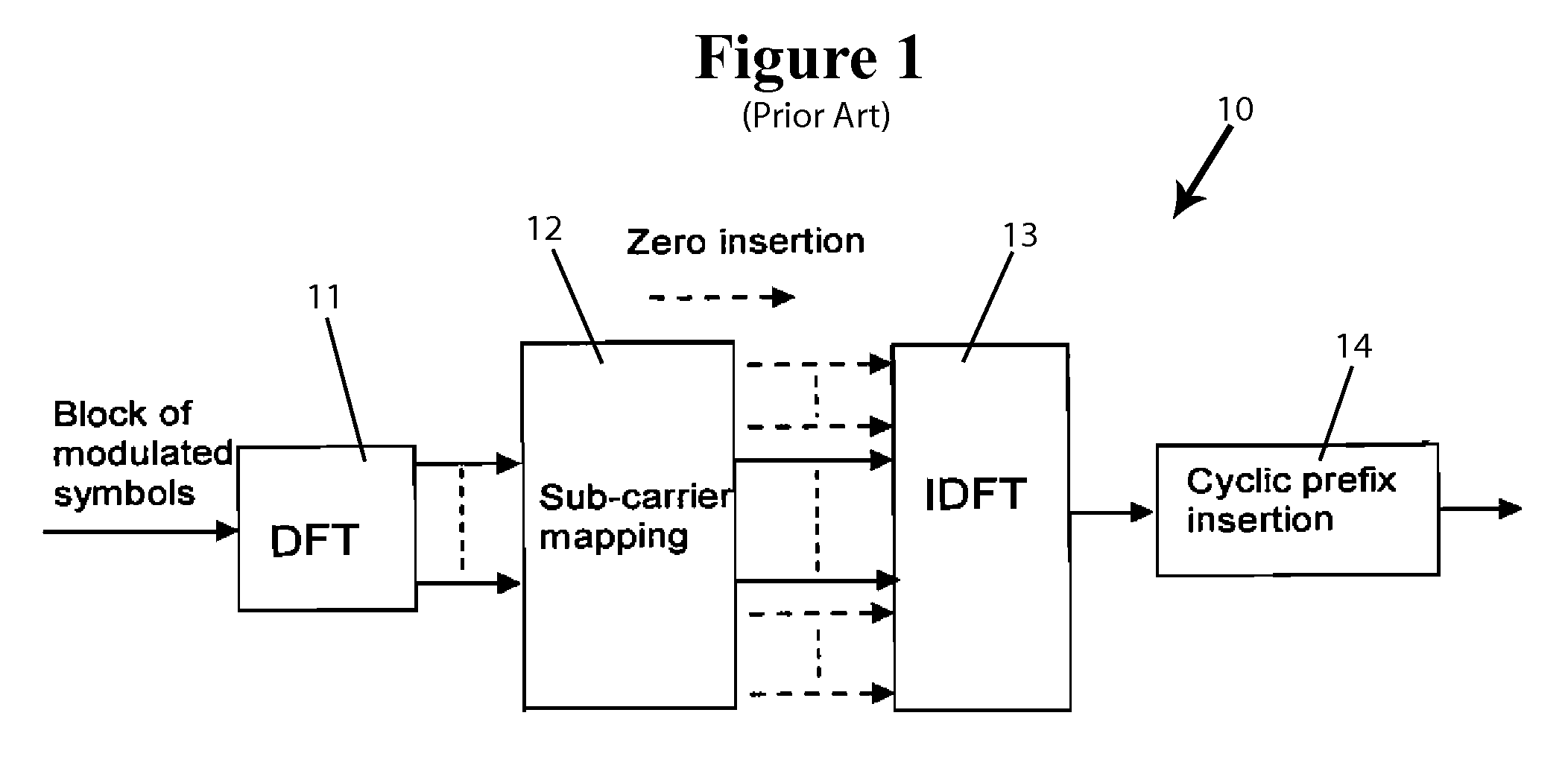
[0024]In FIG. 1 is shown a basic transmitter 10 for DFT-spread OFDM. Blocks of M complex modulated symbols xn, n=0, 1, . . . , M−1, are transformed by a DFT 11 which results in M coefficients Xk:

Xk=∑n=0M-1xn-j2πnkM,k=0,1,…,M-1.(1)

[0025]The output from the DFT is mapped by a sub-carrier mapping module 12 on equidistant sub-carriers lk=l0+kL, where l0 is a frequency offset, and L is an integer larger than or equal to 1. All other inputs to the N-point Inverse Discrete Fourier Transform (IDFT) are set to zero.

[0026]The output of the IDFT 13, yn, is given by

yn=1M∑k=0M-1Xkj2πnlkN,n=0,1,…,N-1(2)

Finally, to avoid inter-symbol interference (ISI) and inter-channel interference (ICI), a cyclic prefix inserter 14 inserts a cyclic prefix, i.e., a copy of the last portion of each OFDM symbol is inserted before the beginning of the same symbol. A time window may be appl...


PUM


Abstract

A method for uplink synchronization of a first transceiver and a second transceiver in a multi-user cellular communication system having communication resources divided into communication channels. The method includes the following steps. A first signature sequence is transmitted from the second transceiver to the first transceiver, where the signature sequence is selected from a first set of signature sequences. In the first transceiver, the received signal is correlated with at least one signature sequence from a second set of signature sequences to estimate the time of arrival of the signature sequence to synchronize transmission between the second transceiver and the first transceiver. In transmitting the first signature sequence from the second transceiver to the first transceiver, the first signature sequence constitutes at least part of a zero-correlation zone sequence.

Description

CROSS REFERENCE TO RELATED APPLICATIONS[0001]This application is a Continuation of PCT / CN2006 / 000077 filed Jan. 18, 2006, which is incorporated by reference in its entirety herein. The PCT application published in English as WO2007 / 082409 A1.FIELD OF THE INVENTION[0002]The disclosure relates to the field of radio communication systems, and in particular to a method for uplink synchronization of a base station and a mobile terminal in a multi-user cellular communication system.BACKGROUND OF THE INVENTION[0003]In most mobile communication systems of today, there are specific requirements regarding synchronization of a base station and a mobile terminal in order to secure a correct data transmission. Examples of such systems are the Universal Terrestrial Radio Access (UTRA) and Evolved UTRA.[0004]In Evolved UTRA, Single-Carrier Frequency Division Multiple Access (SC-FDMA) may be used as multiple access scheme for the uplink communication. The transmission scheme of SC-FDMA is the so-ca...

Claims


Application Information

Patent Timeline
Patent Type & Authority Applications(United States)
IPC IPC(8): H04Q7/20H04W56/00H04W92/10
CPCH04L5/0007H04L5/0048H04L27/2655H04W56/0005H04W56/0085H04J13/0062H04L27/2613H04L27/2675H04J3/0682H04W56/00H04W74/0833H04W92/10
Inventor POPOVIC, BRANISLAVMAURITZ, OSKAR
Owner HUAWEI TECH CO LTD
Why Eureka
Try Eureka