Balanced Belt or Chain Drive for Electric Hybrid Vehicle Conversion

a hybrid vehicle and belt drive technology, applied in the direction of engine-driven generators, electric propulsion mounting, transportation and packaging, etc., can solve the problems of complex application of electric belt or chain drive to many vehicles and inability to sustain the radial tension required

Inactive Publication Date: 2009-01-01
KYDD PAUL HARRIMAN
View PDF33 Cites 32 Cited by
  • Summary
  • Abstract
  • Description
  • Claims
  • Application Information

AI Technical Summary

Benefits of technology

[0008]This invention comprises a balanced belt or chain drive, consisting of a driven pulley or sprocket driven by a toothed timing belt or chain with idler rollers on either side of the driven member such that all the forces on the driven member are balanced except for torque. One or more driving means, preferably two electric motors, engage the belt or chain via drive pulleys or sprockets in such a way that they apply tensioning forces to the belt which offset one another and driving forces which combine with one another to provide torque to the driven member.
[0009]This drive may be applied to provide a flexible speed reduction connection to the drive shaft of a conventional internal combustion engine vehicle to permit operation on either internal combustion or electric power or both together. It is an objective of the present invention to provide such a drive enabling the use of the hybrid drive method disclosed in U.S. Patent Application US2006 / 0030450 A1, Feb. 9, 2006, in vehicles of almost any type having rear-wheel or all-wheel drive.

Problems solved by technology

The application of an electric belt or chain drive to many vehicles is complicated by the fact that the forward universal joint of a single-part drive shaft is relatively inaccessible for the mounting of a drive pulley, and it is supported by a simple bushing at the output end of the transmission shaft extension, which is incapable of sustaining the radial tension required to avoid slippage and skipping in the drive belt or chain.

Method used


Image

  • Balanced Belt or Chain Drive for Electric Hybrid Vehicle Conversion
  • Balanced Belt or Chain Drive for Electric Hybrid Vehicle Conversion
  • Balanced Belt or Chain Drive for Electric Hybrid Vehicle Conversion

Examples


example

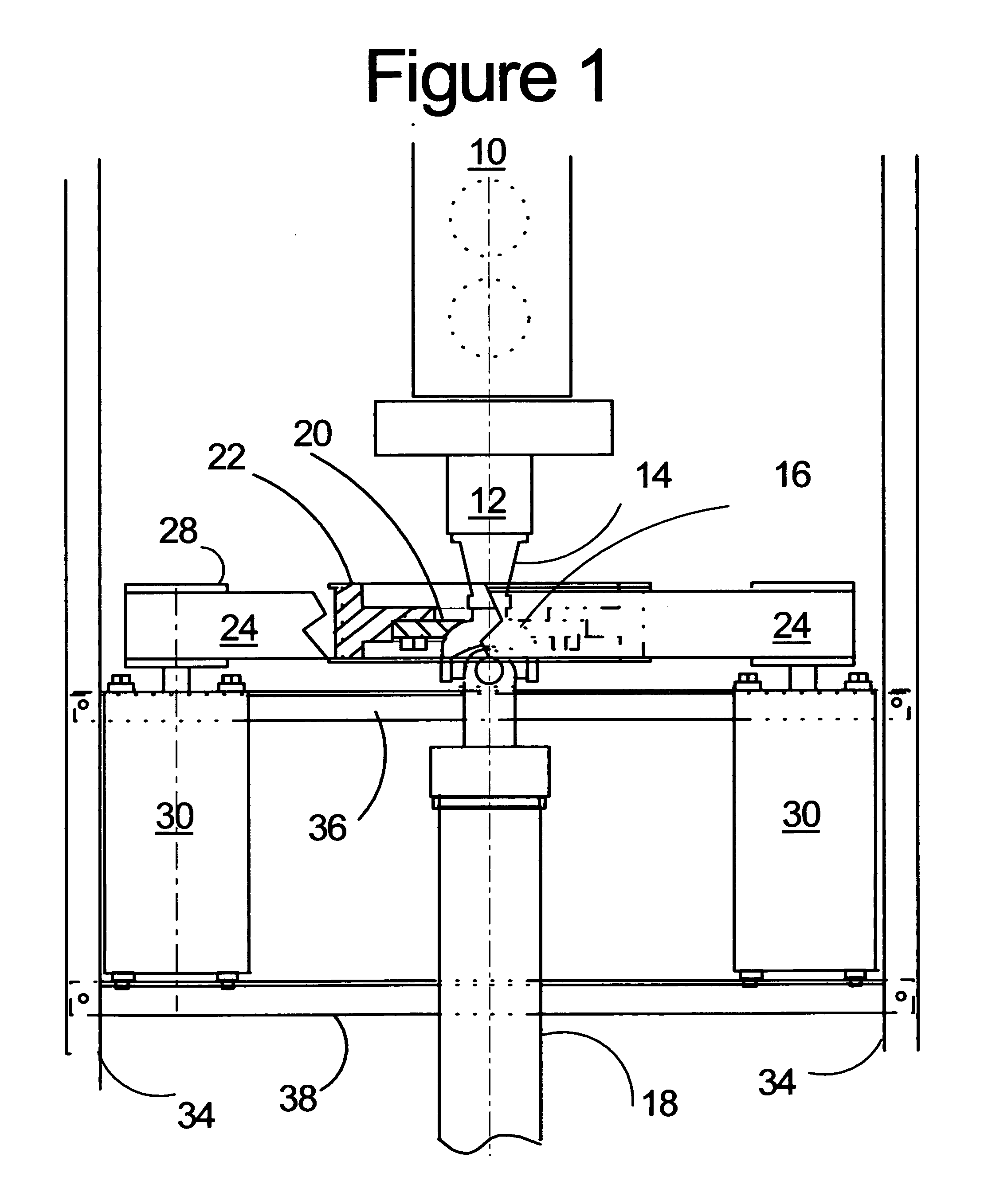
[0042]A 1986 Chevrolet S-10 with a two part drive shaft was converted to a plug-in hybrid by the teachings of U.S. Patent Application US2007 / 0169970 A1 using an Advanced DC FB1 9 inch diameter electric motor, a Curtis 1231 controller and ten GNB group 24 12 V batteries charged by a Zivan NG3 charger. The center bearing mount was strengthened to resist the side force and a chain drive was used to transmit torque form the motor to the drive shaft with tolerance for sidewise displacement of the shaft by the tension in the chain. The vehicle could be run satisfactorily up to 35 miles per hour on electric power only, but the chain drive was noisy and the torque had to be limited by the controller to accommodate the sidewise flexing of the stiffened drive shaft mounting.

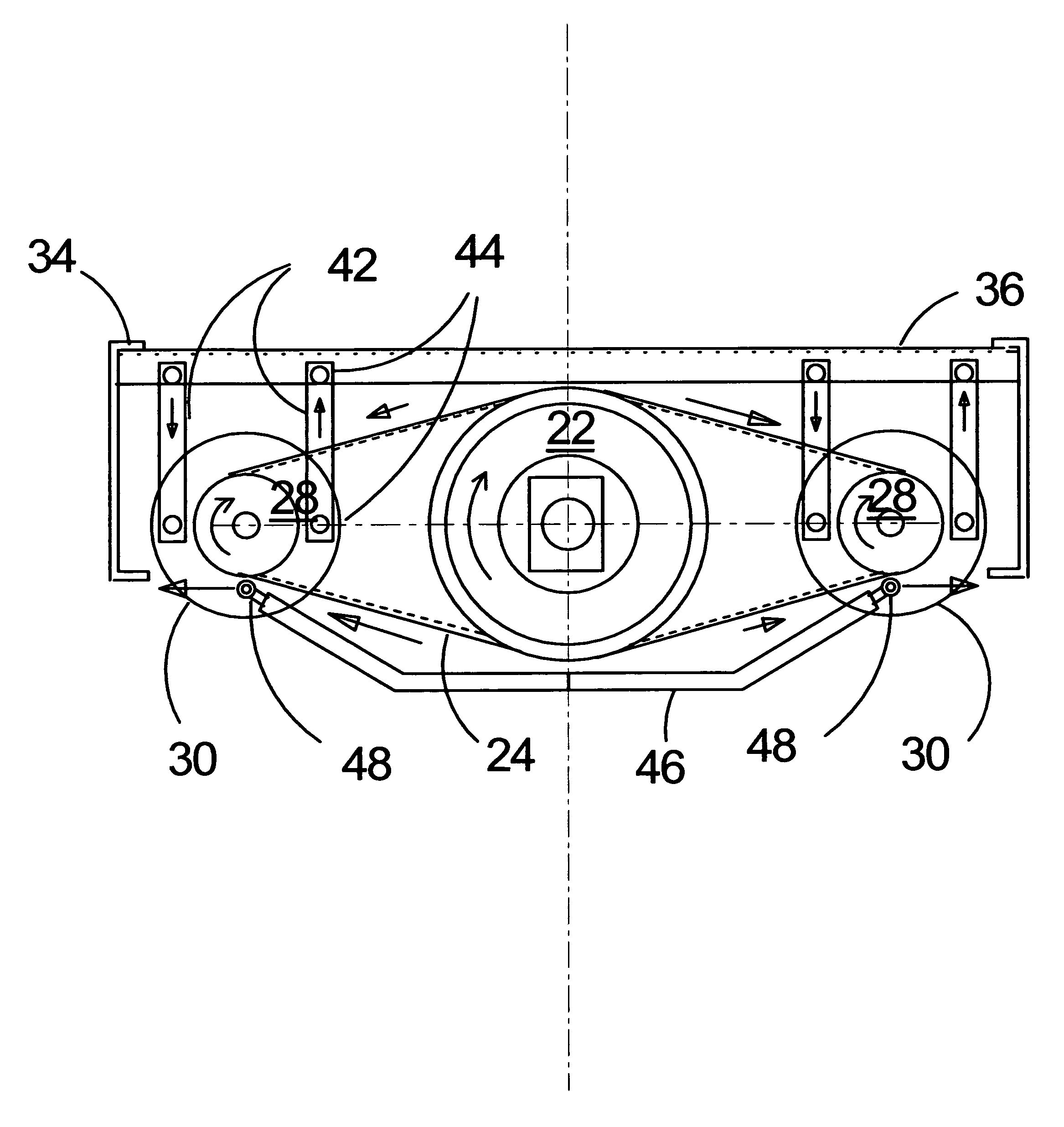
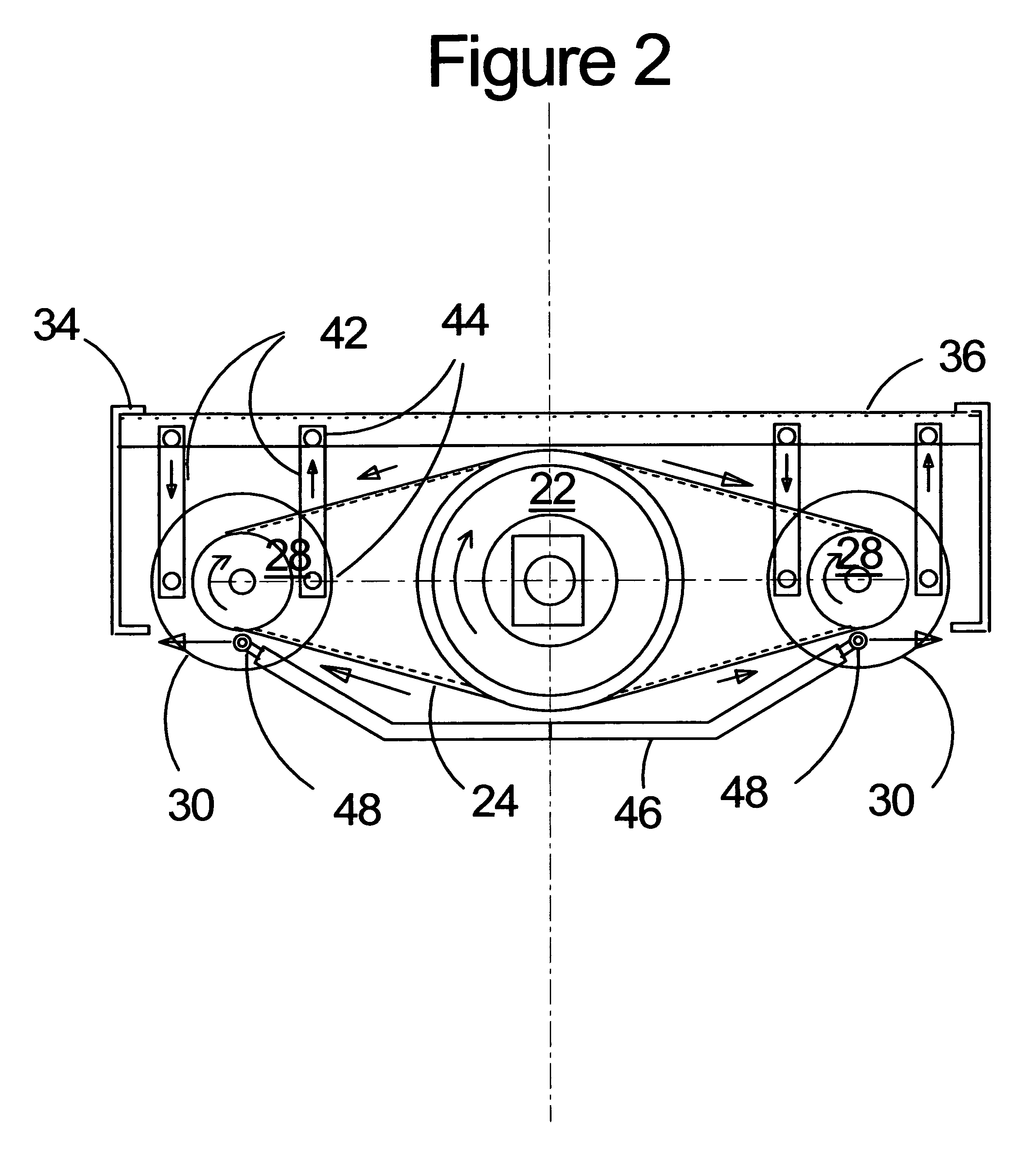
[0043]The vehicle was modified according to the teachings of the present invention by replacement of the single motor by two Advanced DC X91 4003 6.7 inch diameter series wound DC motors driving the shaft via a 2 inch wide...


PUM


Abstract

A drive assembly is described which can apply a pure torque to a driven member while allowing for limited motion of the driven member in the radial direction. This drive assembly is particularly suitable for converting an Internal Combustion (IC) vehicle to an IC-electric hybrid vehicle comprising installation of two electric motors coupled to a drive shaft of the vehicle via the drive of this invention such that the electric motors can provide some or all of the mechanical power required to propel the vehicle while accepting some relative motion between the existing vehicle drive shafts and the chassis and imposing minimal radial force on the drive shaft.

Description

CROSS-REFERENCE TO RELATED APPLICATIONS [0001]This application claims the benefit of U.S. Provisional Patent Application Ser. No. 60 / 761,231 filed Jan. 23, 2006, embodied in U.S. Patent Application US2007 / 0169970 A1, filed Jan. 17 2007, the complete disclosure of which is hereby expressly incorporated by reference, as well as Provisional Patent Application Ser. No. 60 / 900,384 filed Feb. 8, 2007, and Provisional Patent Application 60 / 958,082 Filed Jun. 30, 2007, all by the present inventor. Specifically this application claims the date of Provisional Patent Application 60 / 958,082 for the matter disclosed therein.FEDERALLY SPONSORED RESEARCH[0002]NoneCITED LITERATURE [0003]Kyle, Ronald L., U.S. Patent Application US2006 / 0030450 A1, Feb. 9, 2006[0004]Kydd, Paul H. U.S. Patent Application US2007 / 0169970 A1, Jul. 26, 2007BACKGROUND OF THE INVENTION [0005]This invention is broadly applicable to driving a rotating shaft which must be allowed to move radially to accommodate vibration and mo...

Claims


Application Information

Patent Timeline
Patent Type & Authority Applications(United States)
IPC IPC(8): B60K1/00B60K6/20
CPCB60K1/02B60K6/485B60L11/12B60L11/14Y02T10/648B60L2270/40Y02T10/6226Y02T10/646Y02T10/7077B60L2270/145B60L2200/46B60L50/15B60L50/16Y02T10/62Y02T10/7072Y02T10/64
Inventor KYDD, PAUL HARRIMAN
Owner KYDD PAUL HARRIMAN
Why Eureka
Try Eureka