Charged particle beam apparatus and specimen inspection method

a particle beam and apparatus technology, applied in the field of charged particle beam apparatus and specimen inspection method, can solve the problems of raster scanning shown in fig. 2a without an unscanned location, overlap becomes impossible, and similar problems

Active Publication Date: 2009-01-01
HITACHI HIGH-TECH CORP
View PDF8 Cites 53 Cited by
  • Summary
  • Abstract
  • Description
  • Claims
  • Application Information

AI Technical Summary

Benefits of technology

[0012]An object of the invention is to provide configuration in which high-speed and high-precision calibration is enabled even if a layout of primary beams on a surface of a specimen varies depending upon a condition of inspection and an inspection method using the configuration in a charged particle beam apparatus using multi-beams.

Problems solved by technology

In FIGS. 2A to 2D, five beams are used, however, independent of the number of beams, the problem is similar.
However, when the layout of the primary beams is variant with the ideal layout on the surface of the specimen, raster scanning shown in FIG. 2A without an unscanned location and overlap becomes impossible. FIGS. 2B to 2D show examples of variance in layouts of primary beams.

Method used


Image

  • Charged particle beam apparatus and specimen inspection method
  • Charged particle beam apparatus and specimen inspection method
  • Charged particle beam apparatus and specimen inspection method

Examples


first embodiment

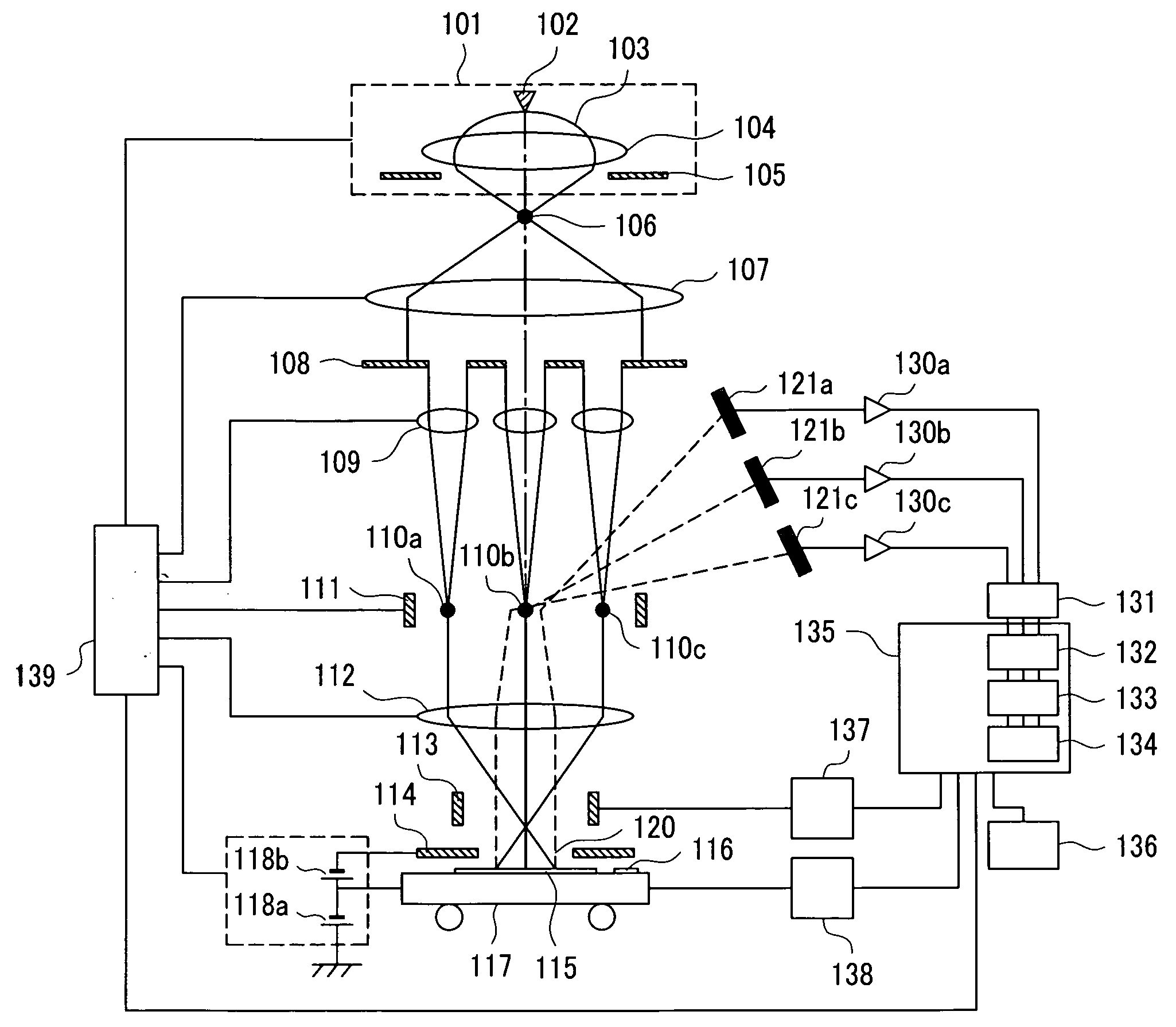
[0037]FIG. 1 shows the schematic configuration of a multi-electron-beam inspection system equivalent to a first embodiment.

[0038]First, the configuration of the system will be described. An electron gun 101 includes a cathode 102 made of a material the work function of which is low, an anode 105 having higher electric potential than the cathode 102 and an electromagnetic lens 104 that superposes a magnetic field upon an accelerating electric field formed between the cathode and the anode. In this embodiment, a Schottky cathode in which emission current is large and the emission of an electron is stable is used. In a downstream direction in which a primary electron beam 103 is extracted from the electron gun 101, as shown in FIG. 1, there are arranged a collimator lens 107, an aperture array 108 plural apertures of which are arranged on the same substance, a lens array 109 having plural apertures, a beam separator 111, an objective lens 112, a deflector for scanning 113, a stage 117 ...

second embodiment

[0078]FIG. 7 shows the schematic configuration of an electron beam inspection system equivalent to a second embodiment.

[0079]When the configuration of the system in this embodiment is compared with that in the first embodiment, an electromagnetic lens 700 is added to a secondary optics system and an image of secondary electrons generated from a wafer 115 which is a specimen is extended and projected on secondary electron detectors 121a to 121c. A secondary beam 120 is rotated or is extended (is reduced) by the effect of an objective lens 112 and the electromagnetic lens 700 and the quantity of the rotation and the extension varies every inspecting condition like a layout when a primary beam reaches a surface of the wafer 115. Then, in this embodiment, the calibration of plural secondary beams is executed at the same time with the calibration of the primary beams.

[0080]FIGS. 8A to 8C are schematic plans showing secondary electron detector positions. When the rotation of plural second...

third embodiment

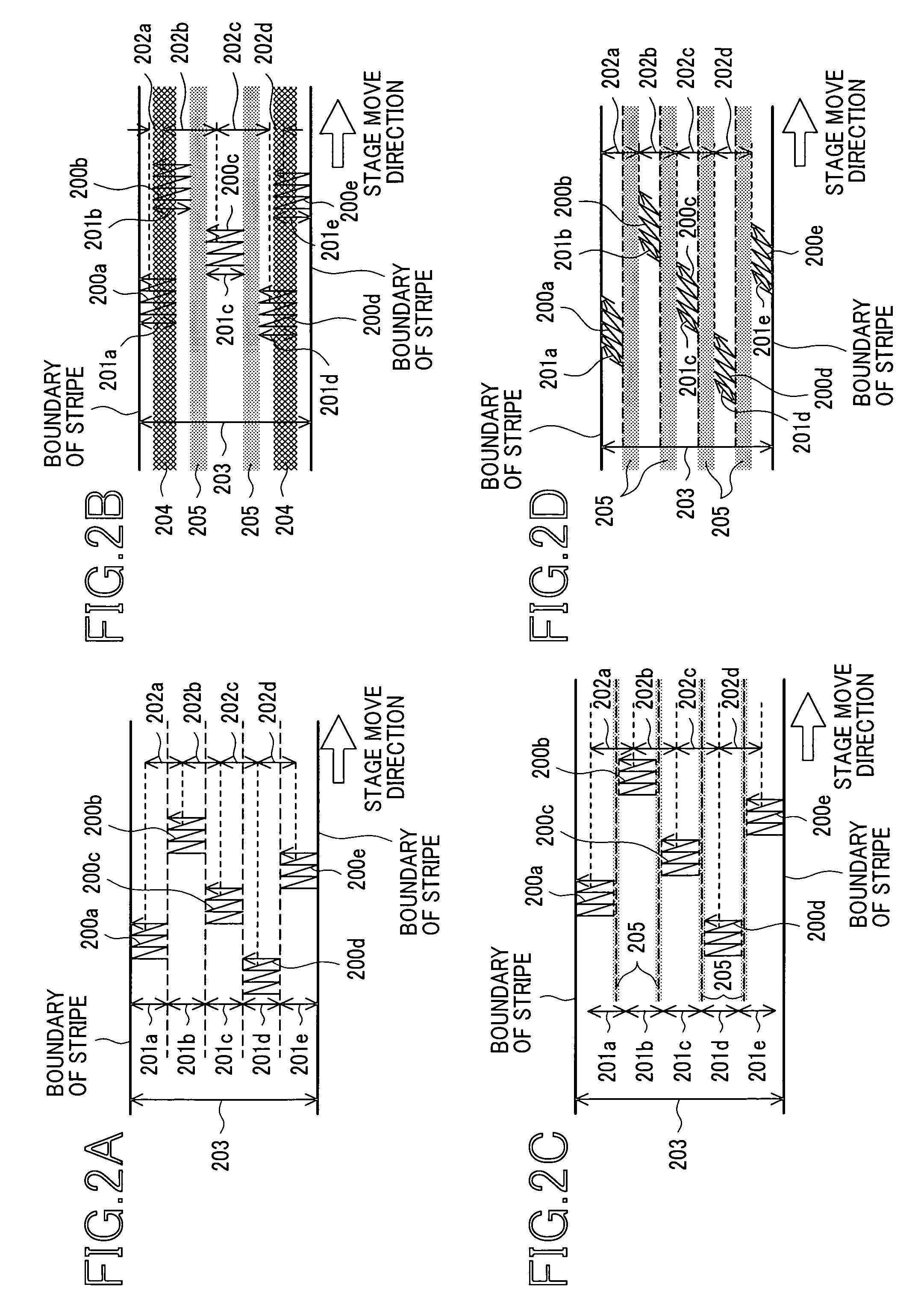
[0089]FIG. 11 shows the schematic configuration of an electron beam inspection system equivalent to a third embodiment.

[0090]When the configuration of the system in this embodiment is compared with that in the first embodiment, an aperture array 1100 and a mechanical operation control unit 1101 are added. Aperture arrays 108 and 1100 which are charged particle beam selecting devices and a lens array 109 are connected to the mechanical operation control unit 1101 and can be mechanically rotated by the control of a system controller 135. FIGS. 12A and 12B are schematic plans showing each aperture array 108, 1100. An aperture of the lens array 109 is similar to the aperture array 108 though the aperture is not shown in FIGS. 12A and 12B and the lens array 109 is rotated according to the rotation of the aperture array 108. At least two apertures are respectively formed in the aperture arrays 108, 1100.

[0091]In FIGS. 12A and 12B, (1) a group of apertures 1200a to 1200e in FIG. 12A and a ...


PUM

PropertyMeasurementUnit
thermal expansion coefficientaaaaaaaaaa
temperatureaaaaaaaaaa
widthaaaaaaaaaa

Abstract

In a multi-charged-particle-beam apparatus, when an electric field and voltage on a surface of a specimen are varied according to characteristics of the specimen, a layout of plural primary beams on the surface of the specimen and a layout of plural secondary beams on each detector vary. Then, calibration is executed to adjust the primary beams on the surface of the specimen to an ideal layout corresponding to the variation of operating conditions including inspecting conditions such as an electric field on the surface and voltage applied to the specimen. The layout of the primary beams on the surface of the specimen is acquired as images displayed on a display of reference marks on the stage. Variance with an ideal state of the reference marks is measured based upon these images and is corrected by the adjustment of a primary electron optics system and others.

Description

CLAIM OF PRIORITY[0001]The present application claims priority from Japanese patent application JP2007-171750 filed on Jun. 29, 2007, the content of which is hereby incorporated by reference into this application.BACKGROUND OF THE INVENTION[0002]The present invention relates to a charged particle beam apparatus, particularly relates to technique for executing high-speed and high-precision inspection using multi-beams.[0003]In a process for manufacturing a semiconductor device and a magnetic disk, there are used an electron beam metrology system that emits a charged particle beam (hereinafter called a primary beam) such as an electron beam and an ion beam on a specimen, acquires a signal of a generated secondary charged particle (hereinafter called a secondary beam) such as a secondary electron and measures a contour and dimensions of a pattern formed on the specimen and an electron beam inspection system that probes whether a defect exists or not.[0004]In such a charged particle bea...

Claims


Application Information

Patent Timeline
Patent Type & Authority Applications(United States)
IPC IPC(8): G01N23/00
CPCH01J37/28G01N23/22
Inventor ENYAMA, MOMOYOOHTA, HIROYA
Owner HITACHI HIGH-TECH CORP
Why Eureka
Try Eureka