
Sheet Metal Oxide Detector

a metal oxide and detector technology, applied in the field of sheet metal oxide detectors, can solve the problems of loss of productivity, overpicking of materials, and scale still remaining on the surface of strips

Inactive Publication Date: 2009-01-01
THE MATERIAL WORKS
View PDF12 Cites 39 Cited by
  • Summary
  • Abstract
  • Description
  • Claims
  • Application Information

AI Technical Summary

Benefits of technology

[0007]The apparatus of the invention and its method of use overcome the disadvantages associated with the prior art testing of processed sheet metal to determine levels of residual oxide scale on the sheet metal surfaces. One embodiment of the apparatus of the invention is designed to be made a part of a sheet metal processing line. This eliminates the prior art process of periodically removing samples of sheet metal from the processing line and taking those samples to a separate laboratory for residual oxide scale testing. (However, some laboratory testing may be required in the initial calibration of the apparatus. Laboratory testing is eliminated as a production tool, and in the present invention laboratory testing is only of value as an independent option for calibration and standardization checks of the apparatus and method of the invention). Thus, the invention provides a time efficient way of real time testing of oxide levels on the surfaces of sheet metal as the sheet metal is being processed. The invention also therefore enables real time adjustments to the processing of the sheet metal to control or manage the level of residual scale on the surfaces of the sheet metal.
[0009]Since surface roughness can influence these measurements of the optical properties, compensation for surface roughness changes will improve the accuracy of the measurement system. This can be done by calibrating the optical sensors either individually or in combination to a particular sheet metal process operating in a restricted range of operating conditions, or preferably by coincident measurement of the surface texture or roughness of the metal surface being tested. The surface roughness sensor of the apparatus of the invention can be a contact or non-contact sensor. Sensors of this type are available in the prior art. Using this method produces a sensor that is independent of the metal processing or the process set points.
[0015]In one embodiment of the apparatus, the laser light source and the reflection detector are paired together as a single sensor unit. A plurality of sensor units that each comprise a laser light source and a reflection detector are arranged side-by-side across the width of the metal strip. The plurality of sensor units effectively monitor the residual oxide scale on the surface of the metal strip moving past the apparatus.
[0016]In an alternate embodiment of the invention, movable scanning optics are positioned relative to the laser light source to receive the beam of laser light from the laser light source and direct the beam of laser light across the width of the metal strip. The scanning optics direct the beam of laser light in a back and forth pattern across the width of the metal strip, thereby effectively monitoring the residual oxide scale across the surface of the metal strip moving past the apparatus.
[0017]In a still further embodiment of the invention, line generating optics are positioned relative to the laser light source to receive the beam of laser light from the laser light source and direct a line of laser light across the width of the metal strip. Alternatively, two or more lines of laser light could be projected on the surface of the metal strip to completely cover the width of the strip. The line or lines of laser light projected across the width of the metal strip effectively monitor the residual scale on the surface of the metal strip moving past the apparatus.
[0018]Each of the embodiments of the apparatus discussed above is incorporated into the sheet metal processing line and provides real time detection of residual oxide scale on the surface of the sheet metal moving through the processing line. This provides a cost efficient and time efficient apparatus and method of detecting residual oxide scale on the surfaces of the sheet metal, and enables real time adjustments to the processing line to achieve a desired level of residual scale.

Problems solved by technology

This prior method of detecting residual scale is problematic in that the method either results in lost productivity when the material processing is running too slowly to obtain the maximum line speed, resulting in overpickling of the material when the processing time becomes excessive, or the material processing running too fast, resulting in some scale still remaining on the surfaces of the strip.
Thus, the problems associated with the prior art visual inspection method for residual scale are problems in the quality of the metal strip produced, and problems in the efficiency of producing the metal strip.
This approach is time consuming and does not allow for the direct, immediate, on-line feedback control of the sheet metal processing.
In addition, the samples taken are discreet and are not necessarily representative of the whole coil of sheet metal being processed where the extent of residual scale could vary from edge to edge or from the beginning to the end of the coil.
Thus, the existing manner of testing for residual scale on the surfaces of processed sheet metal is inefficient and unreliable.

Method used


Image

  • Sheet Metal Oxide Detector
  • Sheet Metal Oxide Detector
  • Sheet Metal Oxide Detector

Examples


Embodiment Construction

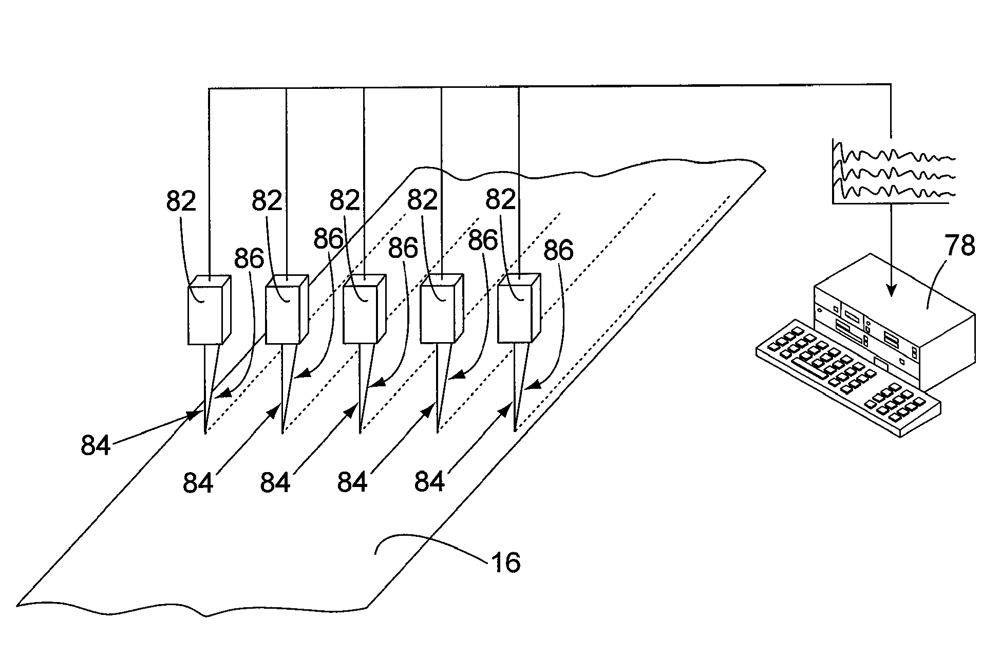
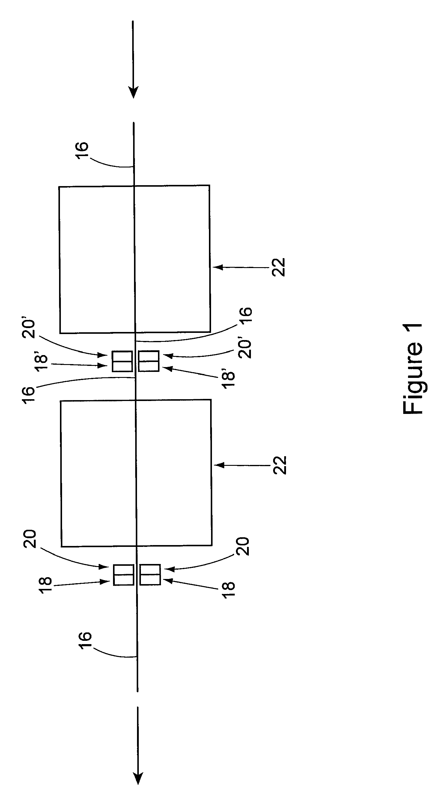
[0025]FIG. 1 shows a schematic representation of a metal processing line in which the apparatus of the invention is used. The processing line of FIG. 1 receives a length of sheet metal and removes scale from the opposite surfaces of the length of sheet metal as the length of sheet metal passes through the processing line. The apparatus of the invention, as will be explained, may be employed in a processing line such as that of FIG. 1 to detect any residual scale remaining on the surfaces of the descaled sheet metal. The processing line shown in FIG. 1 is only one example of an environment in which the apparatus of the invention may be used. Therefore, the processing line of FIG. 1 should not be interpreted as the only environment in which the apparatus may be used. FIG. 1 basically represents a strip of metal 16 that is moving relative to the oxide detector apparatus 18 of the invention, which includes a surface roughness detector or sensor 20, whereby the apparatus 18 detects any r...


PUM

PropertyMeasurementUnit
angleaaaaaaaaaa
areaaaaaaaaaaa
lengthaaaaaaaaaa

Abstract

An apparatus for detecting residual oxide or scale present on a metal surface following pickling or mechanical processing of the metal surface to remove scale makes use of laser light that is reflected off of the metal surface, a reflection detector that detects the absolute reflectivity and polarization of the reflecting laser light, a roughness measurement sensor, and a computerized control system that uses combinations of the information from the three sensors to provide an indication of the scale remaining on the metal surface.

Description

BACKGROUND OF THE INVENTION[0001]1. Field of the Invention[0002]The present invention pertains to an apparatus and method for detecting and quantifying residual oxide or scale present on the surface of processed sheet metal. This is important following or during pickling or mechanical processing of the sheet metal to remove scale. Additional applications evident to those skilled in the art include processes that may influence an existing scale layer on a metal surface, either as part of a process that is designed to produce a controlled surface scale condition, such as the so-called bluing of stovepipe, or in-processes where the production of an oxide surface layer would indicate a problem in the metal surface, such as an annealing process. The apparatus and method of the invention basically make use of combinations of three sensors. The first two sensor configurations use laser light that is reflected off the surface of the process sheet metal. In one system, a reflection detector ...

Claims


Application Information

Patent Timeline
Patent Type & Authority Applications(United States)
IPC IPC(8): G01N21/00G01J4/00G01N21/84
CPCG01N2021/8918G01N21/94
Inventor VOGES, KEVIN C.CRITCHLEY, STUART H.CHUPIL, VICTOR WASYL
Owner THE MATERIAL WORKS
Learn More